


C141-E072-01EN 4 - 13
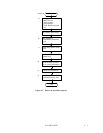
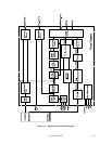
4.6.4 Time base generator circuit
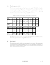
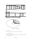
The drive uses constant density recording to increase total capacity. This is different from the
conventional method of recording data with a fixed data transfer rate at all data area. In the
constant density recording method, data area is divided into zones by radius and the data
transfer rate is set so that the recording density of the inner cylinder of each zone is nearly
constant. The drive divides data area into 15 zones to set the data transfer rate. Table 4.2
describes the data transfer rate and recording density (BPI) of each zone.
Table 4.2 Write clock frequency and transfer rate of each zone
Zone 0 1 2 3 4 5 6 7
Cylinder 0
to
1308
1309
to
2616
2617
to
3914
3915
to
4868
4869
to
5648
5649
to
6328
6329
to
7468
7469
to
8248
Transfer rate
[MB/s]
34.67 34.67 34.67 33.57 32.66 31.76 30.25 29.18
Zone 8 9 10 11 12 13 14
Cylinder 8249
to
8638
8639
to
9418
9419
to
10008
10009
to
10598
10599
to
11525
11526
to
12162
12163
to
12554
Transfer rate
[MB/s]
28.63 27.53 26.62 25.70 24.20 23.14 21.47
The MPU transfers the data transfer rate setup data (SDATA/SCLK) to the RDC that includes
the time base generator circuit to change the data transfer rate.
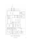
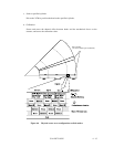
4.7 Servo Control
The actuator motor and the spindle motor are submitted to servo control. The actuator motor
is controlled for moving and positioning the head to the track containing the desired data. To
turn the disk at a constant velocity, the actuator motor is controlled according to the servo data
that is written on the data side beforehand.