


C141-E077-01EN 5 - 25
1) Multiword DMA transfer mode 2:
Sets the FR register = X'03' and SC register = X'22' by the SET FEATURES command
2) Ultra DMA transfer mode 2:
Sets the FR register = X'03' and SC register = X'42' by the SET FEATURES command
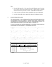
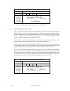
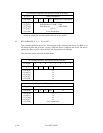
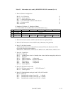
At command issuance (I/O registers setting contents)
1F7
H
(CM) 1 1 0 0 1 0 1 R
1F6
H
(DH)
×
L
×
DV Start head No. /LBA [MSB]
1F5
H
(CH)
1F4
H
(CL)
1F3
H
(SN)
1F2
H
(SC)
1F1
H
(FR)
Start cylinder No. [MSB]/ LBA
Start cylinder No. [LSB] / LBA
Start sector No. / LBA [LSB]
Transfer sector count
xx
R = 0 or 1
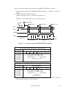
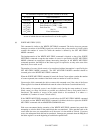
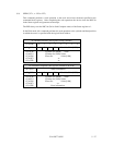
At command completion (I/O registers contents to be read)
1F7
H
(ST) Status information
1F6
H
(DH)
×
L
×
DV End head No. /LBA [MSB]
1F5
H
(CH)
1F4
H
(CL)
1F3
H
(SN)
1F2
H
(SC)
1F1
H
(ER)
End cylinder No. [MSB] / LBA
End cylinder No. [LSB] / LBA
End sector No. / LBA [LSB]
00 (*1)
Error information
*1 If the command is terminated due to an error, the remaining number of
sectors of which data was not transferred is set in this register.
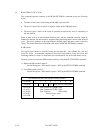
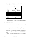
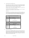
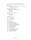
(8) WRITE VERIFY (X'3C')
This command operates similarly to the WRITE SECTOR(S) command except that the device
verifies each sector immediately after being written. The verify operation is a read and check for
data errors without data transfer. Any error that is detected during the verify operation is posted.
At command issuance (I/O registers setting contents)
1F7
H
(CM) 0 0 1 1 1 1 0 0
1F6
H
(DH)
×
L
×
DV Start head No. /LBA [MSB]
1F5
H
(CH)
1F4
H
(CL)
1F3
H
(SN)
1F2
H
(SC)
1F1
H
(FR)
Start cylinder No. [MSB]/ LBA
Start cylinder No. [LSB] / LBA
Start sector No. / LBA [LSB]
Transfer sector count
xx