


C141-E112-01EN 5 - 37
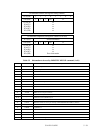
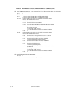
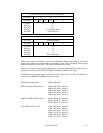
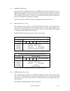
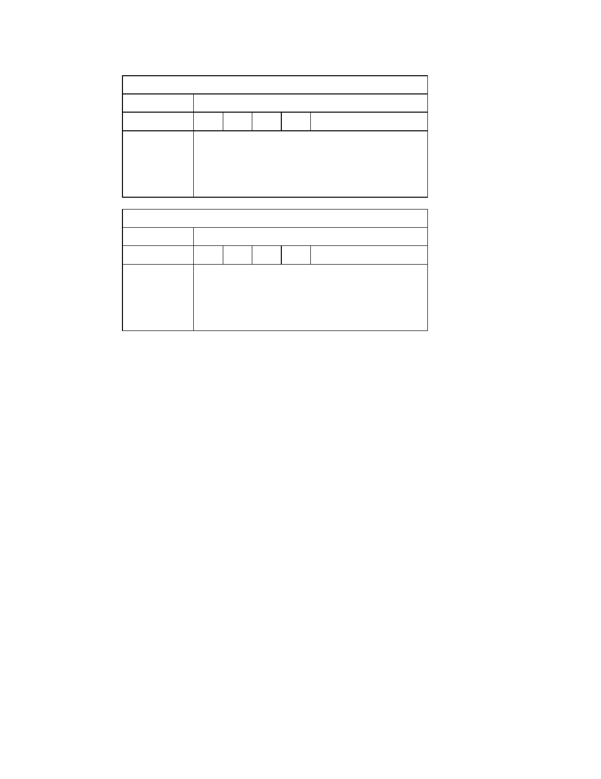
At command issuance (I/O registers setting contents)
1F7
H
(CM) 11101111
1F6
H
(DH)
×××
DV xx
1F5
H
(CH)
1F4
H
(CL)
1F3
H
(SN)
1F2
H
(SC)
1F1
H
(FR)
xx
xx
xx
xx or transfer mode
[See Table 5.6]
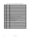
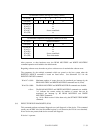
At command completion (I/O registers contents to be read)
1F7
H
(ST) Status information
1F6
H
(DH)
×××
DV xx
1F5
H
(CH)
1F4
H
(CL)
1F3
H
(SN)
1F2
H
(SC)
1F1
H
(ER)
xx
xx
xx
xx
Error information
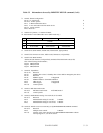
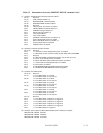
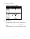
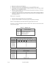
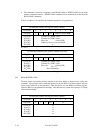
The host sets X'03' to the Features register. By issuing this command with setting a value to the
Sector Count register, the transfer mode can be selected. Upper 5 bits of the Sector Count register
defines the transfer type and lower 3 bits specifies the binary mode value.
However, the IDD can operate with the PIO transfer mode 4 and multiword DMA transfer mode 2
regardless of reception of the SET FEATURES command for transfer mode setting.
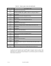
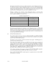
The IDD supports following values in the Sector Count register value. If other value than below
is specified, an ABORTED COMMAND error is posted.
PIO default transfer mode 00000 000 (X‘00’)
PIO flow control transfer mode X 00001 000 (X‘08’: Mode 0)
00001 001 (X‘09’: Mode 1)
00001 010 (X‘0A’: Mode 2)
00001 011 (X‘0B’: Mode 3)
00001 100 (X‘0C’: Mode 4)
Multiword DMA transfer mode X 00100 000 (X‘20’: Mode 0)
00100 001 (X‘21’: Mode 1)
00100 010 (X‘22’: Mode 2)
Ultra DMA transfer mode X 01000 000 (X‘40’: Mode 0)
01000 001 (X‘41’: Mode 1)
01000 010 (X‘42’: Mode 2)
01000 011 (X‘43’: Mode 3)
01000 100 (X‘44’: Mode 4)
01000 101 (X‘45’: Mode 5)