


E-8
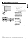
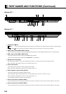
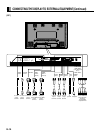
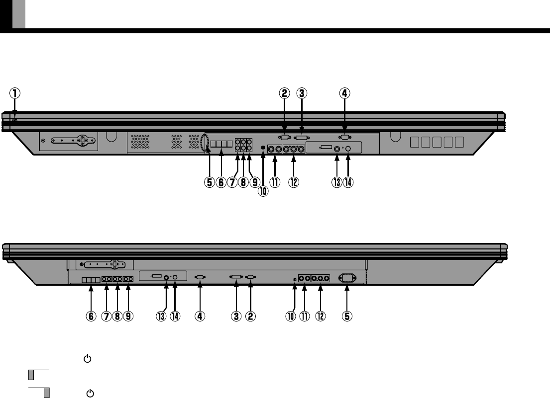
1 OFF/STD-BY switch
OFF :
The power indicator lamp goes off, and the power can’t be turned on by the power button. The power is partly supplied.
STD-BY :The power indicator lamp lights red, and the power can be turned on or off by the power button.
2 RGB 2 input terminal (RGB 2 INPUT/mD-sub)
Connect this terminal to the PC’s display (analog RGB) output terminal or decoder (digital broadcast tuner, etc.) output terminal.
3 RGB 1 input terminal (RGB 1 INPUT/DVI-D)
Connect this terminal to the PC’s display (digital RGB) output terminal
*The connection cable No.88741-8000 made by
molex Inc. is recommanded.
4 RS-232C terminal (RS-232C)
This terminal is provided for you to control the display from the PC. Connect it to the RS-232C terminal on the PC.
When connecting a cable, attach a ferrite core to the cable. (See P. E-13.)
5 Power input terminal
Connect this terminal to the power cable supplied with the display.
When connecting a cable,attach a ferrite core to the cable. (See P. E-13)
6 External speaker output terminal (EXT SP)
Connect this terminal to the optionally available speaker.
(When using other speaker than the optional one, use 6 Ω speaker for 50” type and 4 - 16 Ω for 61” type.)
When connecting a cable,attach a ferrite core to the cable. (See P. E-13)
*See the speaker instruction manual for more information.
7 Sound 3 input terminal (AUDIO 3 INPUT)
Connect this terminal to the sound output terminal of your VCR, etc. (See P.E-37 for the selection of audio input for video input.)
8 Sound 2 input terminal (AUDIO 2 INPUT)
Connect this terminal to the sound output terminal of your VCR, etc. (See P.E-37 for the selection of audio input for video input.)
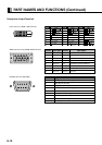
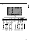
PART NAMES AND FUNCTIONS (Continued)
Bottom (50”)
Bottom (61”)