


Page 3
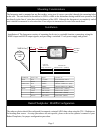
Mounting Considerations
Installation
The Integrator unit is mounted on any at surface, using two #6 screws provided, through the mounting holes
in the case. The unit should be located so its LED is visible to the helmsman during normal boat operation, but
not directly in the line of vision due to the brightness of the LED. Although the Integrator is a completely sealed
unit it should be mounted in a location that is not subject to immersion or water from wash down.
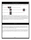
Installation of The Integrator consists of mounting the device in a suitable location, connecting wiring for
NMEA input and AD10 output signals, and providing a switched 12 volt power supply and ground.
Connector
Wire Color Signal Connects To
Power Red + 12 VDC Switched Power Source
Black Ground Engine Ground
NMEA 0183 Red NMEA + Gladiator NMEA Out + (Red)
Black NMEA - Gladiator NMEA Out - (Black)
AD10 Orange AD10 Clock + Furuno Clock + (Yellow)
Green AD 10 Clock - Furuno Clock - (Green)
Blue AD10 Data + Furuno Data + (White)
Brown AD 10 Data - Furuno Data - (Black)
Gladiator
Compass
Ball
Red ( + )
Black ( - )
{
NMEA Out
NMEA Wire
Switched
12 V Pwr
Source
Orange AD10 Clock +
Green Ad 10 Clock - _
Blue AD 10 Data +
Brown AD 10 Data -
Integrator
Wire Color
Connects To
Furuno Clock + (Yellow)
Furuno Clock - (Green)
Furuno Data + (White)
Furuno Data - (Black)
Red ( + )
Black
( - )
Radar/Chartplotter MARPA Con guration
The radar or plotter should be con gured for magnetic oriented AD10 data when using the TR-1 Gladiator as
the heading data source. As setup procedures are unit speci c, please refer to the operator’s manual of your
Radar/Charplotter, for proper con guration procedure.
Red ( + )
Black ( - )