


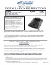

WIRING INSTRUCTIONS
1-800-456-6868
IMPORTANT: Make sure that you have read this entire section before you begin wiring!
•
be wired in-line with the supply voltage (V+) to the docking station.
If you have any installation questions, please call Gamber-Johnson customer support at
•
rated at 10 amp, 32 volt AC/DC fast acting.
of fire replace only with the same type and rating of supplied fuse. The provided fuse is
Caution: For continued protection against risk
If a timing device is used follow the instructions of the manufacturer of that device. It must
•
device conforms to ASTM standard D471 and SAE standard J1128.
personnel using Littlefuse part number FHM1 (Gamber-Johnson part number 11689). This
Caution: If the fuse holder requires replacement it should be replaced by qualified service
battery positive, away from moving parts, and temperatures that exceed 180 degrees F.
The fuse holder location must be kept within 10 inches of the connection to the
crimp tools CT-100, CT-600, CT-1525 or CT-1551.
When assembling the butt splice connectors use only Panduit
provided with fuse holder.
with the dock. Connect the fuse holder to the lead wire using the butt splice connectors
Fuse must be inserted in supplied fuse holder.
• The power connection must be made with the 10 amp in-line fuse and fuse holder provided
•
away from moving parts or areas where high temperatures may occur.
Connection of the supply voltage (V+) must be kept as close to the battery as possible.
•
must conform to SAE standard J1128.
30 feet and
Protect the lead wires from abrasion and chafing by using wire loom or conduit, and route
must not exceed
•
Use only Panduit crimp tool CT-1550 or CT-1551.
the disconnect pigtail.
cap the un-used RED or BLUE wire on
Route the lead wires to the battery. Total wire in the circuit
Using the
CT-1550 OR CT-1551.
,
use only Panduit crimp tools CT-100, CT-600, CT-1525
station. The disconnect must be easily accesible. When assembling the butt splice connectors
to the docking station as possible using the disconnect pigtail provided with the docking
Caution: The butt splice connections must be made as close
wire joint provided with the docking station,
docking station.
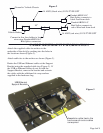
nnect lead wires to the disconnect pigtail using the butt splice connectors provided with the •
docking station to the vehicle's electrical system.
Co
•
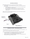
IMPORTANT REMINDERS:
supply voltage (V+) from the vehicle. (The RED wire remains unconnected)
b. By-Pass Installation (Power switch is by-passed) - Connect the BLUE wire to the
supply voltage (V+) from the vehicle. (The BLUE wire remains unconnected)
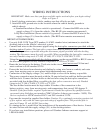
a. Standard Installation (Power switch is operational) - Connect the RED wire to the
vehicle chassis.
2. Attach BLACK ground wire to the location where the vehicle battery grounds to
1. Install docking station into vehicle, making sure that all bolts are tight.
Refer to Figure 2
Use only SAE J1128 Type GPT number 14 AWG stranded wire (minimum) to attach the
Page 5 of 8