


Magnum 6K32T & 6K32TRC Managed Switch Installation and User Guide 05/07)
37
www GarrettCom com
..
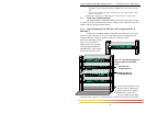
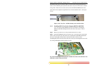
Security violation or an S-Ring Fault, causes the contact to open and thus trigger an
alarm in the user’s monitoring system
The second (bottom position) NC Alarm Contact is held close when there is
power on the main board inside of the 6K32T & 6K32TRC. This provides a “Hardware
Alarm” because the NC contacts will open when internal power is lost, either from an
external power down condition or by the failure of the power supply inside of the
Magnum 6K32T & 6K32TRC Switch. Useful info. about Alarm contacts:
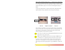
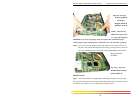
1. There is four terminal block (1,2,3,4)provided next to AC/DC power supply
2. The top two pins (1,2) are software operated
3. The bottom two pins (3,4) are hardware operated
4. By default it is NC (normally closed)
5. The software operation needs to be enabled and set to get the Alarm traps. For detailed
information about the Software Alarm and software control of SNMP alarm traps, please
reference the Magnum MNS-6K Software User Manual. (Chapter 19th).
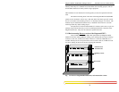
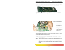
3.5 6K32T & 6K32TRC Port Module (6KPM) Installation
The Magnum 6K32T & 6K32TRC Switches are normally received from the
factory with 24 ports fixed and one required 6KPM module installed. There may be
situations where 6KPM cards need to be added or replaced. In cases where a 6KPM
module needs to be added in the modular slot, the faceplate for an available front-
mounted slot must be removed. The following procedure describes this operation.
3.5.1 Preparation for Installing and Removing 6KPMs
STOP!!!
Be sure the power cord and connections
for all powers single or dual, is unplugged
from the chassis before attempting to remove
and/or replace any PM cards.
Failure to do so may result in damage to the unit
and will void the warranty.
Caution- Avoid Static Discharge: Opening of the 6K32TRC chassis can only be
performed by trained service persons. The port modules (like most
electronic equipment) are sensitive to static discharge. Use proper ESD
measures when handling port modules.
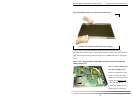
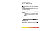
Step 1. Make sure the 6KPM Card package has all necessary accessories to install it
properly. Each 6KPM Card package for field installation contains
(Daughterboard (Bigger) and Granddaughter board (smaller), three 5/8 stand
offs for the Granddaughter board, six #4-40 Pan-Head screws along with a