


Magnum DS80F & DS80C Dual-speed Stackable Hubs Installation and User Guide (12/01)
13
www GarrettCom com
..
properly attached, the brackets will extend slightly below the base of the unit to allow clearance
for the rubber feet.
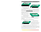
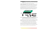
3.2 Connecting Ethernet Media
The Magnum DS80C Dual-Speed Personal Hub can be connected to two media types
i.e. 100BASE-TX and 10BASE-T, however, DS80F can be connected to the following three
media types: 100BASE-TX, 10BASE-T and 100BASE-FX. CAT 5 cables should be used when
making 100BASE-TX connections. When the ports are used as 10BASE-T ports, CAT 3 may be
used. In either case, the maximum distance for unshielded twisted pair cabling is 100 meters
(328 ft). For fiber port 100BASE-FX multi-mode, 50/125 or 62.5/125 microns cabling can be
used, whereas for single-mode, 9/125 microns cabling should be used. Fiber cabling supports
much longer cable distance and higher bandwidths as compared to copper wiring.
Media IEEE Standard
Connector
Twisted Pair (CAT 3 or 5) 10BASE-T RJ-45
Twisted Pair (CAT 5) 100BASE-TX RJ-45
Fiber (Multi-mode) 100BASE-FX ST
Fiber (Multi-mode) 100BASE-FX SC
Fiber (Single-mode) 100BASE-FX SC
Fiber (Multi-mode) 100BASE-FX MTRJ
NOTE : It is recommended that high quality CAT. 5 cables (which work for both 10Mbps and
100Mbps) be used whenever possible in order to provide flexibility in a mixed-speed
network, since dual-speed ports are auto-sensing for either 10 and 100Mbps. Note
that the auto-sensing function does not sense the cable type.
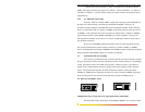
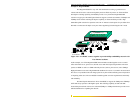
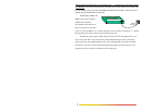
3.2.1 Connecting Twisted Pair (RJ-45, CAT 3 or CAT 5, Unshielded or Shielded)
The following procedure describes how to connect a 10BASE-T or 100BASE-TX
twisted pair segment to the RJ-45 port. The procedure is the same for both unshielded and
shielded twisted pair cables.
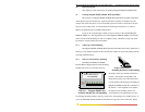
1. Using standard twisted pair media, insert either end of the cable with a RJ-45 plug into
the RJ-45 connector of the port. Note that, even though the connector is shielded, either
unshielded or shielded cables and wiring may be used.
2. Connect the other end of the cable to the corresponding device.
3. Use the LINK LED to ensure proper connectivity by noting that the LED will be
illuminated when the unit is powered and proper connection is established. If this does
not help, ensure that the cable is connected properly and that the device on the other end
is powered and is not defective.
4. For Port # 1SW, if the LINK LED is not illuminated, move the switch which has a cross-
over or up-link for linking to another hub.