


Magnum DS880 Dual-Speed Stackable Hubs Installation and User Guide (05/01)
14
www GarrettCom com
..
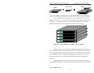
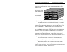
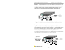
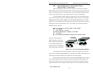
3.1.2 Wall (or Vertical Surface) Mounting
Each Magnum DS880 Dual-Speed Hub is shipped with two metal mounting brackets
(and screws) to allow the unit to be mounted in nearly any desired orientation or position. The
brackets are attached to the metal hub case using one of the metal screws for each bracket and
attaching to the Magnum DS880 through the round hole of the bracket. A user-supplied screw
attaches the bracket to the mounting surface. It is recommended that the brackets be attached to
two opposite corners of the unit. When properly attached, the brackets will extend slightly
below the base of the unit to allow clearance for the rubber feet and the cooling fan exhaust.
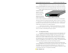
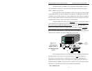
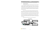
3.2 Connecting Ethernet Media
The Magnum DS880 Dual-Speed Stackable Hubs can be connected to the following
two media types: 100BASE-TX and 10BASE-T. CAT 5 cables should be used when making
100BASE-TX connections. When the ports are used as 10BASE-T ports, CAT 3 may be used.
In either case, the maximum distance for unshielded twisted pair cabling is 100 meters (328 ft).
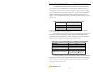
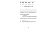
Media
IEEE Standard Connector
Twisted Pair (CAT 3) 10BASE-T RJ-45
Twisted Pair (CAT 5) 100BASE-TX RJ-45
NOTE : It is recommended that high quality CAT. 5 cables (which work for both 10Mb and
100Mb) be used whenever possible in order to provide flexibility in a mixed-speed
network, since dual-speed ports are auto-sensing for either 10 and 100Mb/s.
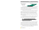
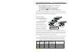
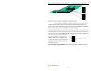
3.2.1 Connecting Twisted Pair (RJ-45, CAT 3 or CAT 5, Unshielded or Shielded)
The following procedure describes how to connect a 10BASE-T or 100BASE-TX
twisted pair segment to the RJ-45 port. The procedure is the same for both unshielded and
shielded twisted pair cables.
1. Using standard twisted pair media, insert either end of the cable with an RJ-45 plug into
the RJ-45 connector of the port. Note that, even though the connector is shielded, either
unshielded or shielded cables and wiring may be used.
2. Connect the other end of the cable to the corresponding device.
3. Use the LINK LED to ensure proper connectivity by noting that the LED will be
illuminated when the unit is powered and proper connection is established. For Port #
8, if the LINK LED is not illuminated, change the setting of the up-link switch. If this
does not help, ensure that the cable is connected properly and that the device on the
other end is powered and is not defective.