


Magnum P62-Series Hardened Switches Installation and User Guide (12/02)
24
www GarrettCom com
..
3.2.6 Connections to NICs which support Auto-Negotiation, RJ-45 ports
The copper ports of Magnum P62-Series Hardened Switches will function properly with
NICs (Network Interface Cards) which support Auto-Negotiation, and the Fast Link Pulse (FLP)
coding for the 100BASE-TX signaling system. When connecting a NIC to a P62, it may be
necessary to reload the NIC drivers on the user device if the NIC has been communicating with a
protocol other than 100BASE-TX (such as 10BASE-T). When 100Mb speed is agreed and in use,
the 10/100 LED is steady ON. It is OFF if there is no traffic or if 10 Mbps traffic.
3.3 Powering the Magnum P62-Series Hardened Switch
3.3.1 Power P62F and mP62 models, for –48V and 24V DC pwr input
Each Magnum Model P62-Series Hardened Switch requires a DC power source, from 20-
70VDC. The wide range of power input qualifies this product for use both in 24VDC as well as -
48VDC environments. The 24VDC or -48VDC power input provides an Ethernet networking
product utilizing a special type of power supply with a proven high-reliability record.
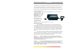
DC Power Terminals: “+”, “
-”, internally
floating
GND: Terminal for “earth” or ground wire
connection to the P62 chassis
Input Voltage: 20 to 70 VDC
Input current: 0.7 amp max.
Power Consumption: 10 watts typical
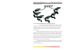
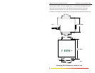
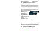
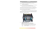
P62 -48V, 24VDC INSTALLATION
This section describes the proper
connection of the -48VDC leads (or 24VDC
leads) to the DC power terminal block on
the Magnum P62 Switch (as shown in
Figure above)
The DC terminal block on the Magnum P62-Series Hardened Switch is located on the left front of
the unit and is equipped with three (3) screw-down lead posts. The power terminals are identified
as positive (+) and negative (-), and they are floating inside the unit so that either may be
grounded by the user if desired. The chassis is “earth” or ground (GND).
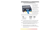
The connection procedure is straightforward. Simply insert the DC leads to the Switch’s
power terminals, positive (+) and negative (-) screws. The use of Ground (GND) is optional; it
connects to the Switch chassis. Ensure that each lead is securely tightened.
NOTE: Always use a voltmeter to measure the voltage of the incoming power supply and
figure out the +ve potential lead or -ve potential lead. The more +ve potential lead will connect
to the post labeled “+ve” and the rest to the “-ve”. The GND can be hooked up at the last.
When power is applied, the green PWR LED will illuminate.