


Checkpoints
A checkpoint is either a byte or word value output to I/O port 80h. The BIOS outputs checkpoints throughout
bootblock and Power-On Self Test (POST) to indicate the task the system is currently executing. Checkpoint
sare very useful in aiding software developers or technicians in debugging problems that occur during the pre-
boot process.
Viewing BIOS checkpoints
Viewing all checkpoints generated by the BIOS requires acheckpoint card, also referred to as a POST card
or POST diagnostic card. These are ISA or PCI add-in cards that show the value of I/O port 80h on a LED
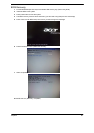
display. Checkpoints may appear on the bottom right corner of the screen during POST. This display method
islimited, since it only displays checkpoints that occur after the video card has been activated.
Bootblock Initialization Code Checkpoints
The Bootblock initialization code sets up the chipset, memory, and other components before system memory
is available. The following table describes the type of checkpoints that may occur during the bootblock
initialization portion of the BIOS.
NOTE: Please note that checkpoints may differ between different platforms based on system configuration.
Checkpoints may change due to vendor requirements, system chipset or option ROMs from add-in
PCI devices.
63
Chapter4
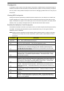
Checkpoint Description
Before D0
If boot block debugger is enabled, CPU cache-as-RAM functionality is enabled at this
point. Stack will be enabled from this point.
D0
Early Boot Strap Processor (BSP) initialization like microcode update, frequency and
other CPU critical initialization. Early chipset initialization is done.
D1
Early super I/O initialization is done including RTC and keyboard controller. Serial port
is
enabled at this point if needed for debugging. NMI is disabled. Perform keyboard
controller BAT test. Save power-on CPUID value in scratch CMOS. Go to flat mode
with 4GB limit and GA20 enabled.
D2 Verify the boot block checksum. System will hang here if checksum is bad.
D3
Disable CACHE before memory detection. Execute full memory sizing module. If
memory sizing module not executed, start memory refresh and do memory sizing in
Boot block code. Do additional chipset initialization. Re-enable CACHE. Verify
that flat mode is enabled.
D4 Test base 512KB memory. Adjust policies and cache first 8MB. Set stack.
D5
Bootblock code is copied from ROM to lower system memory and control is given to it.
BIOS now executes out of RAM. Copies compressed boot block code to memory in
right segments. Copies BIOS from ROM to RAM for faster access. Performs main
BIOS checksum and updates recovery status accordingly.
D6
Both key sequence and OEM specific method is checked to determine if BIOSrecovery
is forced. Main BIOS checksum is tested. If BIOS recovery is necessary,control
flows to checkpoint E0. See Bootblock Recovery Code Checkpoints sectionfor more
information.
D7
Restore CPUID value back into register. The Bootblock-Runtime interface module is
moved to system memory and control is given to it. Determine whether to execute
serial flash.
D8
The Runtime module is uncompressed into memory. CPUID information is stored in
memory.
D9
Store the Uncompressed pointer for future use in PMM. Copying Main BIOS into
memory. Leaves all RAM below 1MB Read-Write including E000 and F000 shadow
areas but closing SMRAM.