


GENERAL
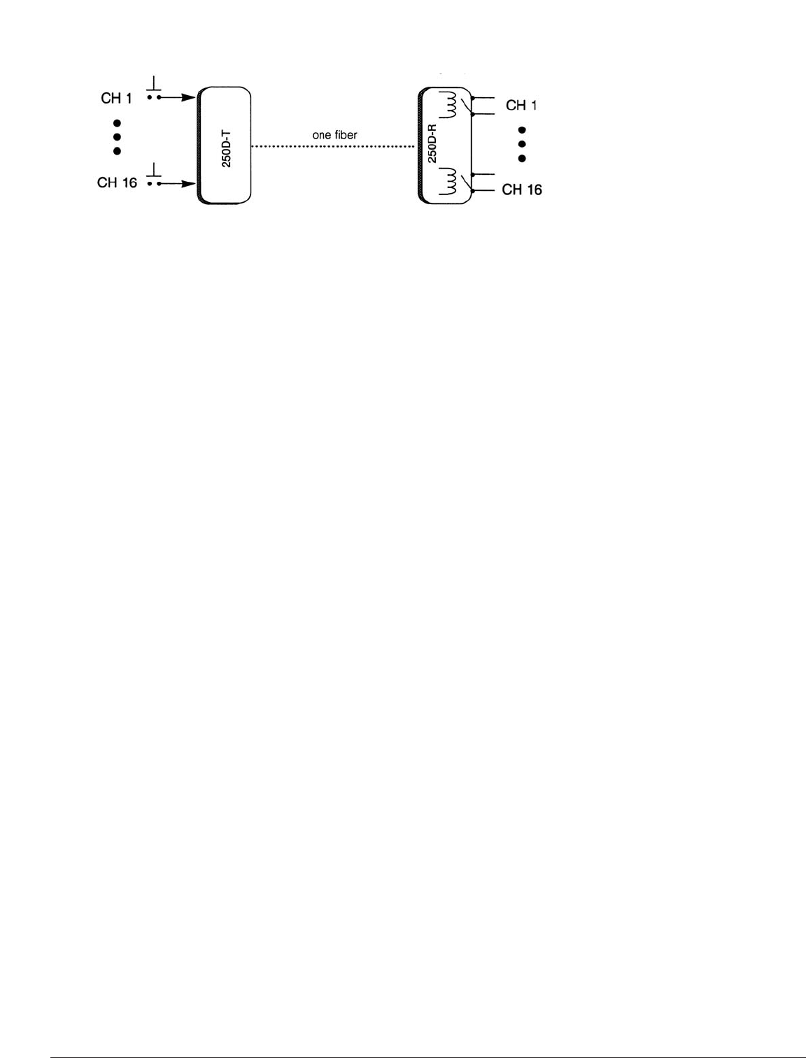
The GE Security 250D system transmits up to 16 channels of low-speed digital data, switch/status
information, or control/function signals. The user may program the receiver to provide 16 channels
of alternate-action outputs , or eight channels of each type. Outputs are TTL drivers or N/O
reed relays.
ABOUT THE SYSTEM
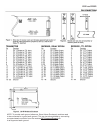
Units are designed for rack mounting in the GE Security Card Cage, 517R Racking System, or in the
501R Miniature Enclosure. If you have ordered standalone units, they have been shipped in a 501R
(figure 3, page 3).
Each unit occupies one card-cage slot. Units in the 515R or the 517R are powered from the rack.
If using the 501R Miniature Rack, the GE Security power supply, model number 613P is required
(or
der
ed separately). Inputs to the transmitter, thr
ough the 44-pin connector
, are normally held high
to +5 volts by means of a 1K ohm pull-up resistor. A closure to ground or an open collector to ground
will activate a particular channel. The r
eceiver has a corresponding dry closure or TTL output for each
channel. The r
elays ar
e normally open and the TTL is normally low. Any number of channels up to 16
may be activated at any time. The transmitter’s closure need only be momentary, alternate action, or
a combination of momentary and alternate action.
TTL OUTPUTS
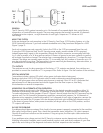
The receivers are set for relay operation at the factory. If TTL outputs are desired, four switches are
provided to conv
ert the channels to TTL in groups of four. Refer to figure 1 for the location of the switches.
OPTICAL INDICA
TORS
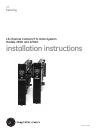
Transmitters include a status LED which, when green, indicates data is being sent.
Receivers include a LEVEL/LOSS indicator which is used to determine received optical power.
This LED will glow green when sufficient optical power is received. If this LED is off, it indicates that
optical power is not being received and would suggest that the fiber is open or, less likely,
the transmitter or receiver is inoperative.
MOMENT
AR
Y OR AL
TERNATE ACTION OPERATION
Receiver outputs may be set in the field by the user for the desired operating conditions, either 16
channels of momentary operation, 16 channels of alternate action, or eight channels of each type.
T
o mak
e adjustments, locate jumper
s E0 and E1 (figur
e 1 abov
e) found near the 8031 pr
ocessor on the
receiver card. For 16 channels of momentary operation, remove both jumpers. For 16 channels of
alternate action operation, install both jumpers. For 8 channels of each type of operation, remove the
E0 jumper and install the E1 jumper. Units are shipped with both units installed (all-alternate-action).
In the ev
ent of pow
er failur
e, when pow
er is restored, all relays will be in the OPEN position, and the
TTL outputs will be low.
IN CASE OF PROBLEMS
If problems should be encountered, first check to be sure power is properly connected to the modules.
Also verify that the fiber is good. Then, check the transmitter status indicators. If lit, data is present.
Check the Lev
el/Loss indicator
s on the r
eceivers. If they are green, the fiber optic cable connection
is functional.
If any pr
oblems arise, please contact the GE Security customer ser
vice depar
tment and hav
e the
following information available: exact model number, product code, and serial numbers of your fiber
optic links, and a listing of the diagnostic indicators and their respective color/condition.
250D and 2250D