


Installation Instructions
10
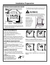
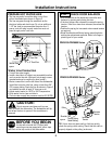
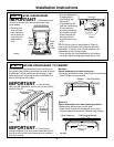
STEP 13 CONNECT WATER SUPPLY
Connect water supply line to 90° elbow.
• Slide compression nut, then ferrule over end of
water line.
• Insert water line into 90° elbow.
• Slide ferrule against elbow and secure with compres-
sion nut.
IMPORTANT – Check to be sure
that door spring does not rub or contact the fill hose or
water supply line. Test by opening and closing the door.
Re-route the lines if a rubbing noise or interference
occurs.
Figure CC
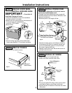
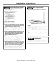
• If a longer drain hose is required, add up to 42" of
length for a total of 10 ft. to the factory installed hose.
Use 5/8" or 7/8" inside diameter hose and a coupler to
connect the two hose ends. Secure the connection
with hose clamps.
Figure DD
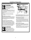
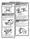
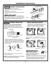
STEP 14 CONNECT DRAIN LINE
FOLLOW ALL LOCAL CODES AND ORDINANCES.
The drain hose molded end will fit 5/8", 3/4" or 1"
diameter connections on the air gap, waste tee or
disposer. Cut on the marked line as required for your
installation.
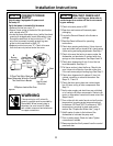
DRAIN LINE INSTALLATION
• Connect drain line to air gap, waste tee or disposer
using either previously determined method.
Waste Tee Installation
Method 1 – Air gap with waste tee or disposer
Disposer Installation
Waste Tee Installation
Method 2 – Built-in “High drain loop” with waste tee or
disposer
Disposer Installation
Figure FF
Figure GG
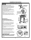
• Secure the drain hose to the air gap, waste tee or
disposer with clamps.
NOTE: TOTAL DRAIN HOSE LENGTH MUST NOT EXCEED
10 FEET FOR PROPER DRAIN OPERATION.
IMPORTANT –
When connecting drain line to
disposer, check to be sure that drain
plug has been removed. DISH-
WASHER WILL NOT DRAIN IF PLUG IS LEFT IN PLACE.
TIP: Avoid unnecessary service call charges. Always be
sure disposer drain plug has been removed before
attaching dishwasher drain hose to the disposer.
Figure EE
Cutting Lines
1"
3/4"
5/8"
IMPORTANT: Do not cut corrugated
portion of hose
18"
Min.
18"
Min.
90° Elbow
Ferrule
90° Elbow
Hot Water
Supply Line
Compression Nut
Door Spring
Remove
Hopper
Plug
Hose Clamp
Coupler
Hose Clamp