


4
4-8 State Logic Processor for Series 90-30 PLC User’s Guide – March 1998
GFK-0726B
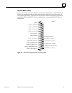
a45091
2
1
3
4
5
6
7
8
9
10
11
12
13
15
16
17
18
19
20
21
22
23
24
25
14
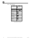
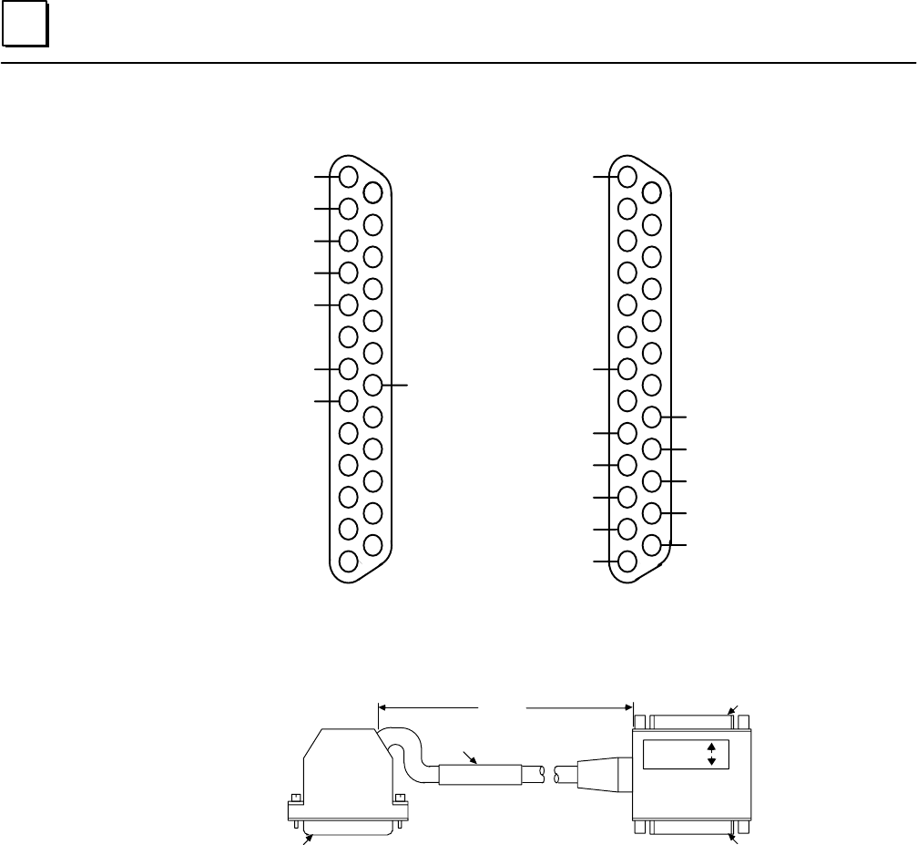
RS–232 DTR
SHIELD
RS–232 TD
RS–232 RD
RS–232 RTS
RS–232 CTS
SIGNAL GROUND
RS–232 DCD
2
1
3
4
5
6
7
8
9
10
11
12
13
15
16
17
18
19
20
21
22
23
24
25
14
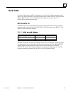
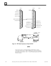
RS–485 SD ( B )
RS–485 RTS ( B )
RS–485 CTS ( B’ )
TERMINATION ( RD )
RS–485 RD ( B’ )
SHIELD
SIGNAL GROUND
RS–485 SD ( A )
RS–485 RTS ( A )
RS–485 CTS ( A’ )
TERMINATION ( CTS )
RS–485 RD ( A’ )
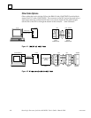
PORT 1 PORT 2
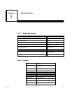
1 FOOT
a44225
PORT 1
PORT 2
PCM COMM. CABLE
IC693CBL305B
RS–232
25–PIN FEMALE-
CONNECTOR
PIN 1
PIN 1
RS–232/RS–485
25–PIN FEMALE
CONNECTOR
LABEL
PIN 1
RS–232
25–PIN MALE
CONNECTOR
(+2.0 INCH, –0 INCH)
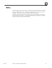
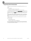
Figure 4-4. WYE Cable Connections for Series 90-30 SLP
NOTE
In the drawing above, the SD (Send Data) and RD (Receive Data)
connections are the same as TXD and RXD used in other terminologies.
(A) and (B) are the same as - and +. A’ and B’ denote inputs, and A and
B denote outputs.