


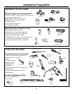


Installation Preparation
PARTS SUPPLIED:
Remove the hardware accessory bag and other parts
from inside or taped to the outside of the dishwasher.
Check contents against illustrations to insure that all
parts are included.
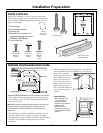
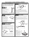
2-piece toekick
6 screws (see illustration)
2 leveling legs
Template for the installation of a
custom panel packed with models
ZBD7000 and ZBD7005 only
Junction box cover
5
2-Piece Toekick with
Sound Insulation
2 Leveling Legs
Screws A
(2) Countertop
Mounting
Screws
Screws B
(2) Cabinet
Mounting
Screws
Screws C
(2) Color
Matched
Toekick
Screws
Junction
Box Cover
with screws
Template
for
ZBD7000
ZBD7005
Only
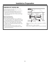
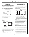
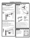
PREPARE DISHWASHER ENCLOSURE
*Models ZBD7000 and ZBD7005 with custom panels are 24-3/4" deep
• The rough cabinet opening must be at least 24” deep,
23-7/8”min. to 24-1/4” wide. The height should be 34”
min. and 35” max.
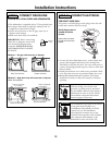
Note: ADA installation, beneath 34" high countertops may be accom-
plished by removing front leveling legs. Drain hose, water and
electrical must be routed through the cutout on the back of the
dishwasher.
• The dishwasher must be installed so that drain hose is
no more than 10 feet in length for proper drainage.
• The dishwasher must be fully enclosed on the top, sides
and back, but should not support any part of the
enclosure.
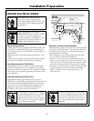
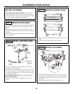
Corner Installation
• When installing into a
corner, allow 2" min.
clearance between
dishwasher and adjacent
cabinet or wall.
• Allow 24-1/8" min.
clearance from the front
of the dishwasher for door
opening.
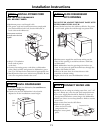
• The floor inside the opening must be even and level
with the finished floor of the kitchen. If the kitchen
floor is tile, it may be
higher than the floor of
the installation cutout.
Pieces of wood may be
placed into the cutout
floor to make it level or
higher than the room
floor. This will allow easy
removal for any future
service.
24-1/8"
Countertop
Dishwasher
Clearance for Door
Opening 2" Minimum
34" to 35"
Underside
of Countertop
to Floor
This Wall Area
must be Free of
Pipes or Wires
23-7/8" Min.
24-1/4" Max
1-3/4"
24"
Min.
6"
20-1/2"
Insulation
Template with Mounting Hardware