


2
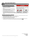
NOTE ON NEUTRAL BONDED GENERATORS: Some portable generators are intended for use on jobsites and are subject to OSHA regulations for GFCI protection on all receptacles.
These "contractor grade" generators have their neutral wire bonded to the ground wire to pass OSHA inspection. When connected to a transfer switch, this may cause nuisance tripping
of the generator GFCI breaker. When using a neutral bonded generator to power a house or building through a transfer switch, consult the generator manufacturer or local authorized
service dealer to determine if the neutral bond wire on the generator can be disabled without voiding the warranty. If it can be disabled, then no modifications to your transfer switch
installation are needed. If the neutral bond cannot be removed or voids the warranty, you must install a Switched Neutral Kit (SNK, Generac model 6297) accessory with your transfer
switch. NOTE: Removal of the neutral bond should be performed by an authorized generator service dealer or qualified electrician. If the neutral bond is removed, the generator will no
longer pass OSHA inspection for job sites.
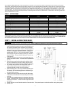
TABLE 1 - SPECIFICATIONS
MODEL: 6382
6335
UTILITY MAIN breaker, Included
200 Amp 200 Amp
GEN MAIN breaker, included
30 Amp 50 Amp
Max Load per Circuit
As marked As marked
Max Load on Generator
30 Amp 50 Amp
Max Watts @ 250 Volt
7500 12,500
Max Watts @ 125 Volt
7500 12,500
Max 1-pole Circuits *
12 12
Max 2-pole Circuits *
6 6
NEMA Configuration of Power Inlet
L14-30 CS6365
Voltage
125/250 Volts 125/250 Volts
NEMA Type Enclosure
3R – Outdoor 3R – Outdoor
Phase
1 1
Minimum Gauge Cord Size
10/4 AWG 6/4 AWG
*NOTE: If Ground Fault Circuit Interrupting (GFCI) breakers, Arc-Fault breaker or surge protecting circuit breakers are used in the transfer switch, they will reduce the
maximum number of circuits from the number shown in the table above. Also if circuit breakers larger than 50 amps are used as sub-feed breakers, the maximum number of
circuit breakers will also be reduced. Contact your local installer or dealer for more information on GFCI, Arc-Fault and Surge Protecting circuit breakers. Because GFCI and
AFCI circuit breakers can take up more than one space, the overall maximum number of circuits may be reduced from the number shown.
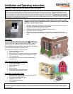
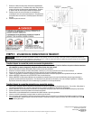
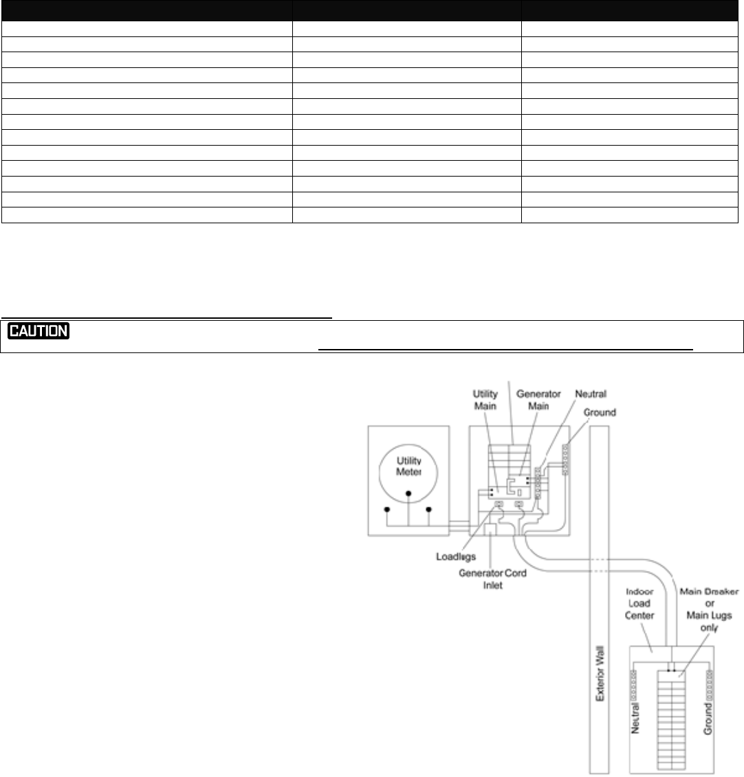
STEP 1: INSTALLATION PROCEDURE:
HAZARDOUS VOLTAGES ARE PRESENT INSIDE TRANSFER SWITCH ENCLOSURES THAT CAN CAUSE DEATH OR SEVERE PERSONAL INJURY. FOLLOW PROPER INSTALLATION,
OPERATION AND MAINTENANCE PROCEDURES TO AVOID HAZARDOUS VOLTAGES. TURN OFF THE MAIN CIRCUIT BREAKER IN THE LOAD CENTER BEFORE STARTING INSTALLATION.
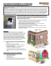
1. Although this transfer switch can be installed above, below or on either side of the utility meter socket, the preferred location is to the RIGHT of the
meter socket since the location of the lugs for the Utility Main are on
the Left side of the transfer switch. Knockouts (KO) are provided
only in the bottom of the enclosure. However, since the enclosure is
aluminum, it is easy to cut in the desired knockout. If the KO is cut
in above the live terminals of the circuit breakers, a watertight hub
should be used. NOTE: If a 2” KO is cut in the side of the Transfer
switch enclosure, the dead front panel may need to be “notched” to
clear the 2” fittings. The back of the KO must be 3/8” from the rear
of the enclosure.
2. Loosen the thumb screw from the cover of the transfer switch, and
slide the cover down to remove. The thumb screw stays attached to
the cover.
3. Remove the two screws from the bottom of the dead front. When
the cover is pulled forward, the snap-in closing plates will fall out.
Set the front cover and dead front aside for reinstallation after wiring.
4. The mounting holes in the back of the transfer switch are on 16”
centers so they could line up on your studs if desired. We
recommend using all four holes to mount the enclosure.
5. Select the bottom center 2” KO to exit to the Main distribution panel.
Terminate the LOAD wires in the landing lugs on the bottom of the
bus assembly, one to the Neutral lug and one to the Ground lug on
the right side of the enclosure.
6. Terminate wires from the meter socket into the utility Main breaker
on the left side, and the Neutral into the unused lug on the insulated
neutral bar.
7. Plug in and wire any additional branch circuit breakers in the spaces
provided. Installer will need to remove any hold-down strap to insert
additional circuit breakers. Re-install hold-down strap after breakers
are inserted.
8. Reinstall dead front cover and interlock mechanism if removed earlier. Fill any unused spaces in the dead front with the closing plates provided.
9. Reinstall cover.