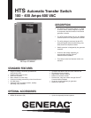
HTS 100-400 Amp
INTERCONNECTIONS
SwitchesandIndicators:
• SystemReadyLED • StandbyOperatingLED
• SwitchPositionLED’s • UtilityAvailableLED
• TestSwitch • FastTestSwitch
• ReturntoNormalSwitch • SafetyDisconnectSwitch
StandbyAcceptVoltage...............................................................................................................................................................................85-95%
StandbyAcceptFrequency..........................................................................................................................................................................85-95%
NominalVoltage............................................................................................................................................................................ 1VoltIncrements
AllowableDeviationofUtility........................................................................................................................................................................1-100%
LineInterruptionDelay.......................................................................................................................................................................1-10Seconds
EngineWarmupTime.......................................................................................................................................................................1-300Seconds
MinimumRunTime............................................................................................................................................................................. 5-60Minutes
ReturntoUtilityTimer.......................................................................................................................................................................... 1-30Minutes
EngineCooldownTimer...................................................................................................................................................................... 1-30Minutes
SignalBeforeTransferTimer..............................................................................................................................................................1-30Seconds
TransferType................................................................................................................................................................InphaseTimeDelayNeutral
PhaseDifferenceforInphaseTransfer.............................................................................................................................................-7+0Degrees
WITHSTAND CURRENT – 600 VOLT HTS SERIES
HTS RATED AMPS 100 150 200 300 400
FUSEPROTECTED
MaximumRMSSymmetrical
FaulCurrent–Amps 200,000 200,000 200,000 200,000 200,000
MaximumFuseSize–Amps 200 400 400 600 600
FuseClass J,T J,T J,T J,T J,T
CIRCUITBREAKERPROTECTED
MaximumRMSSymmetrical
FaultCurrent–Amps 14,000 25,000 25,000 35,000 35,000
ProtectiveDeviceContinuous
Rating(Max.)–Amps 150 300 300 600 600
•TestedinaccordancewiththewithstandandclosingrequirementsofUL1008andCSAStandards.
•Currentratingsarelisted@480VAC.
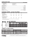
UNIT DIMENSIONS
HTS VOLTAGE ENCLOSURE ENCLOSURE WALL MOUNT ENCLOSURE WEIGHT
RATED HEIGHT WIDTH BOLT PATTERN DEPTH (lbs.)
AMPS H W M1 M2 D1 D2
100 ALL 36 24 18 37.5 12.7 10 180
150-200 120/240 36 24 18 37.5 12.7 10 185
150-200 120/208 36 24 18 37.5 12.7 10 185
150-200 277/480 48* 30* 24 49.5 14.8 12 265
300-400 120/240 36 24 18 37.5 12.7 10 245
300-400 120/208 36 24 18 37.5 12.7 10 245
300-400 277/480 48* 30* 24 49.5 14.8 12 325
HTS RATED CONTACTOR TERMINALS(1LUGPERPOLE) NEUTRAL BAR* GROUND LUG (1PROVIDED)
AMPS LUG WIRE RANGE # LUGS LUG WIRE RANGE LUG WIRE RANGE
100 2/0–14AWG 4 2/0–14AWG 2/0–14AWG
150 400MCM–4AWG 4 350MCM–6AWG 350MCM–6AWG
200 400MCM–4AWG 4 350MCM–6AWG 350MCM–6AWG
300 600MCM–4AWG 4 600MCM–4AWG 350MCM–6AWG
or2–[250MCM–1/0AWG] [250MCM–1/0AWG]** 350MCM–6AWG
400 600MCM–4AWG 4 600MCM–4AWG 350MCM–6AWG
or2–[250MCM–1/0AWG] [250MCM–1/0AWG]**
TERMINAL LUG WIRE RANGES
*NotincludedinHTSwithswitchedneutral.**Allowablewirerangeinbracketsisfor2wiresperlug.
Generac Power Systems, Inc. • S45 W29290 HWY. 59, Waukesha, WI 53189 • generac.com
©2009 Generac Power Systems, Inc. All rights reserved. All specifications are subject to change without notice. Bulletin 0171250SBY/Printed in U.S.A. 08.05, rev: 03.09


