


2 of 2
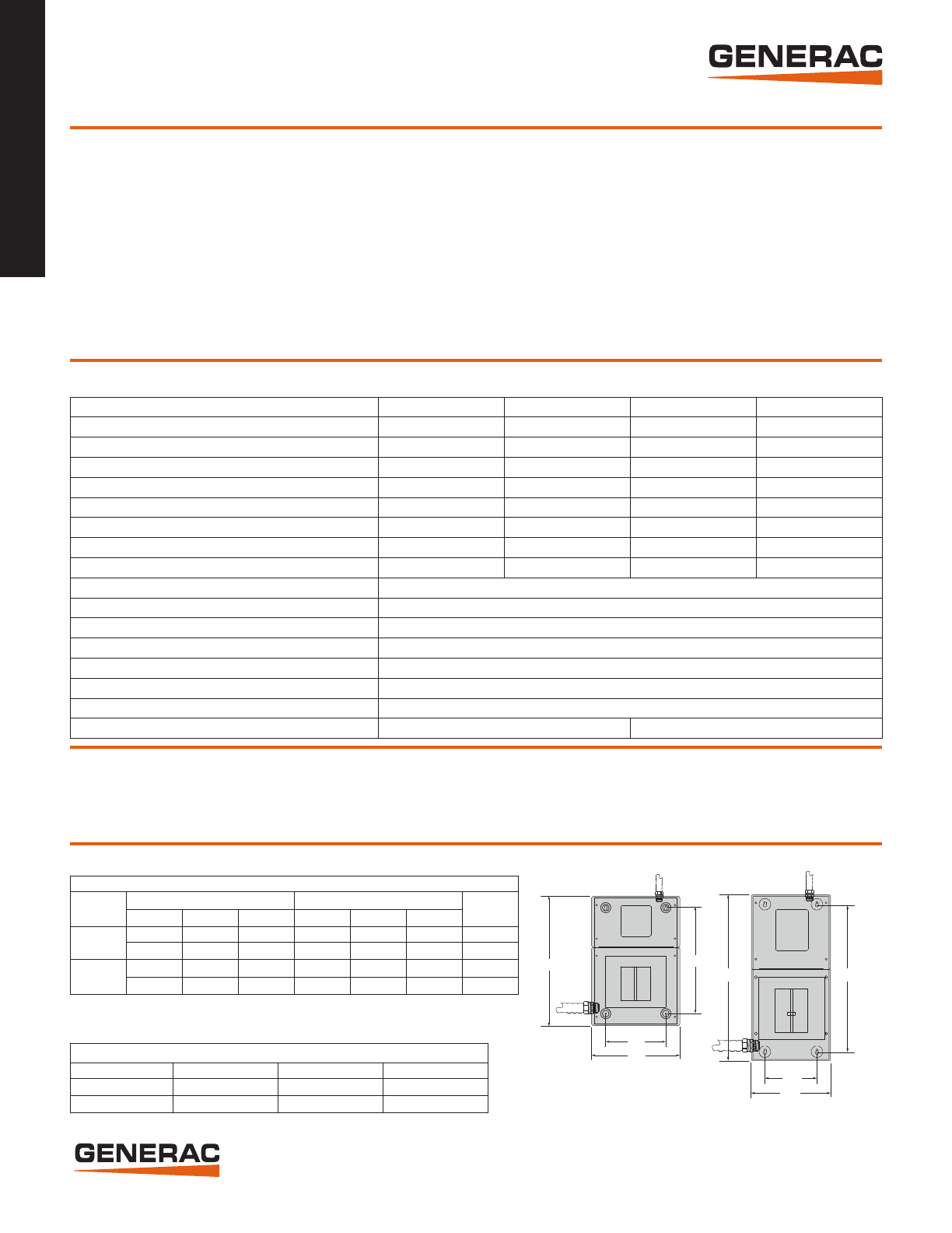
Dimensions and Wire Ranges
®
Generac Power Systems, Inc. • S45 W29290 HWY. 59, Waukesha, WI 53189 • generac.com
©2013 Generac Power Systems, Inc. All rights reserved. All specifications are subject to change without notice. Bulletin 0199020SBY-C Printed in U.S.A. 04/17/13
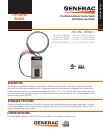
50-100 Amps Pre-Wired Switch
®
Functions
Specifications
Features
• Electrically operated, mechanically-held contacts for fast, positive connections.
• Rated for all classes of load, 100% equipment rated, both inductive and resistive.
• 2 pole, 250 VAC contactors.
• 30 millisecond transfer time.
• Dual coil (100A) and single coil (50A) designs.
• Main contacts are silver plated or silver alloy to resist welding and sticking.
• NEMA 1 (indoor rated) enclosure is standard.
• 5 Year Limited Warranty.
All timing and sensing functions originate in the generator controller.
Utility voltage drop-out ......................................................................................................................................................................................................................<60%
Timer to generator start ..................................................................................................10 second factory set, adjustable between 2-1500 seconds by a qualified dealer*
Engine warm up delay ................................................................................................................................................................................................................. 5 seconds
Standby voltage sensor ..................................................................................................................................................................................................60% for 5 seconds
Utility voltage pickup .........................................................................................................................................................................................................................>80%
Re-transfer time delay ...............................................................................................................................................................................................................15 seconds
Engine cool-down timer ............................................................................................................................................................................................................60 seconds
Exerciser .............................................................................................................................................................................................................. 12 minutes every 7 days
The transfer switch can be operated manually without power applied.
*When used in conjunction with units utilizing Evolution™ controls
Model RTG10EZA1 RTG12EZA1 RTG14EZA1 RTG16EZA1
Voltage 120/240, 1ø 120/240, 1ø 120/240, 1ø 120/240, 1ø
Amps 50 50 100 100
Circuits, 50A, 240V – – – 1
40A, 240V – 1 1 1
30A, 240V 1 1 – –
20A, 240V 1 – 1 1
20A, 120V 3 3 6 5
15A, 120V 3 5 4 5
Phase 1
Rated AC Frequency 60 Hz
Enclosure Material Steel
Enclosure Type NEMA 1
Withstand Rating (Amps) 10,000
Lug Range 1/0 - #14
Load Transition Type Open Transition
30' Whip Conductor Gauges (Hot, Neutral, Ground, Control) 8, 8, 10, 18 6, 6, 8, 18
H1
W1
W2
H2
Pre-Wired Switch
Mechanical Dimensions
Amps
Height Width
Depth
H1 H2 H3 W1 W2 W3
50*
18.5 in. 22.5 in. 22 in. 10.5 in. 15.4 in. 14.4 in. 3.8 in
470mm 571.8mm 558.8mm 266.7 392mm 366mm 97.5mm
100
23.5 in. 26.4 in. N/A 8.3 in. 12.6 in. N/A 6.3 in.
597mm 671.7mm N/A 211mm 320.7mm N/A 159.6mm
Wire Ranges
Amps Conductor Lug Neutral Lug Ground Lug
50 1/0 - #14 2/0 - #14 2/0 - #14
100 2/0 - #14 2/0 - #14 2/0 - #14
50 Amp Switch
100 Amp Switch
H1
W1
W2
H2
*Note: The 50 Amp switch is flush mountable. H1 and W1 refer to mounting hole spacing.
H2 and W2 are cover dimensions. H3 and W3 (not shown in diagram) are the enclosure
dimensions without cover.