


Generac
®
Power Systems, Inc. 3
2.1 INTRODUCTION TO INSTALLATION
This equipment has been wired and tested at the
factory. Installing the switch includes the following
procedures:
• Mounting the enclosure.
• Connecting power source and load leads.
• Connecting the generator start circuit.
• Connecting any auxiliary contact (if needed)
• Installing/connecting any options and accessories.
• Testing functions.
2.2 UNPACKING
Carefully unpack the transfer switch. Inspect closely
for any damage that might have occurred during
shipment. The purchaser must file with the carrier any
claims for loss or damage incurred while in transit.
Check that all packing material is completely
removed from the switch prior to installation.
2.3 MOUNTING
Mounting dimensions for the transfer switch
enclosure are in this manual. Enclosures are
typically wall-mounted. See “Mounting Dimensions”.
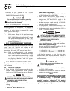
Handle transfer switches carefully when
installing. Do not drop the switch. Protect the
switch against impact at all times, and against
construction grit and metal chips. Never
install a transfer switch that has been
damaged.
Install the transfer switch as close as possible to the
electrical loads that are to be connected to it. Mount
the switch vertically to a rigid supporting structure.
To prevent switch distortion, level all mounting
points. If necessary, use washers behind mounting
holes to level the unit.
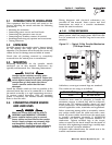
2.4 CONNECTING POWER SOURCE
AND LOAD LINES
Make sure to turn OFF both the UTILITY
(NORMAL) and EMERGENCY (STANDBY)
power supplies before trying to connect
power source and load lines to the transfer
switch. Supply voltages are extremely high
and dangerous. Contact with such high
voltage power supply lines causes extremely
hazardous, possibly lethal, electrical shock.
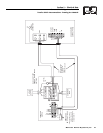
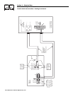
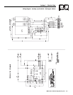
Wiring diagrams and electrical schematics are
provided in this manual. Power source and load
connections are made at a transfer mechanism,
inside the switch enclosure.
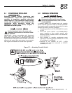
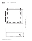
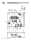
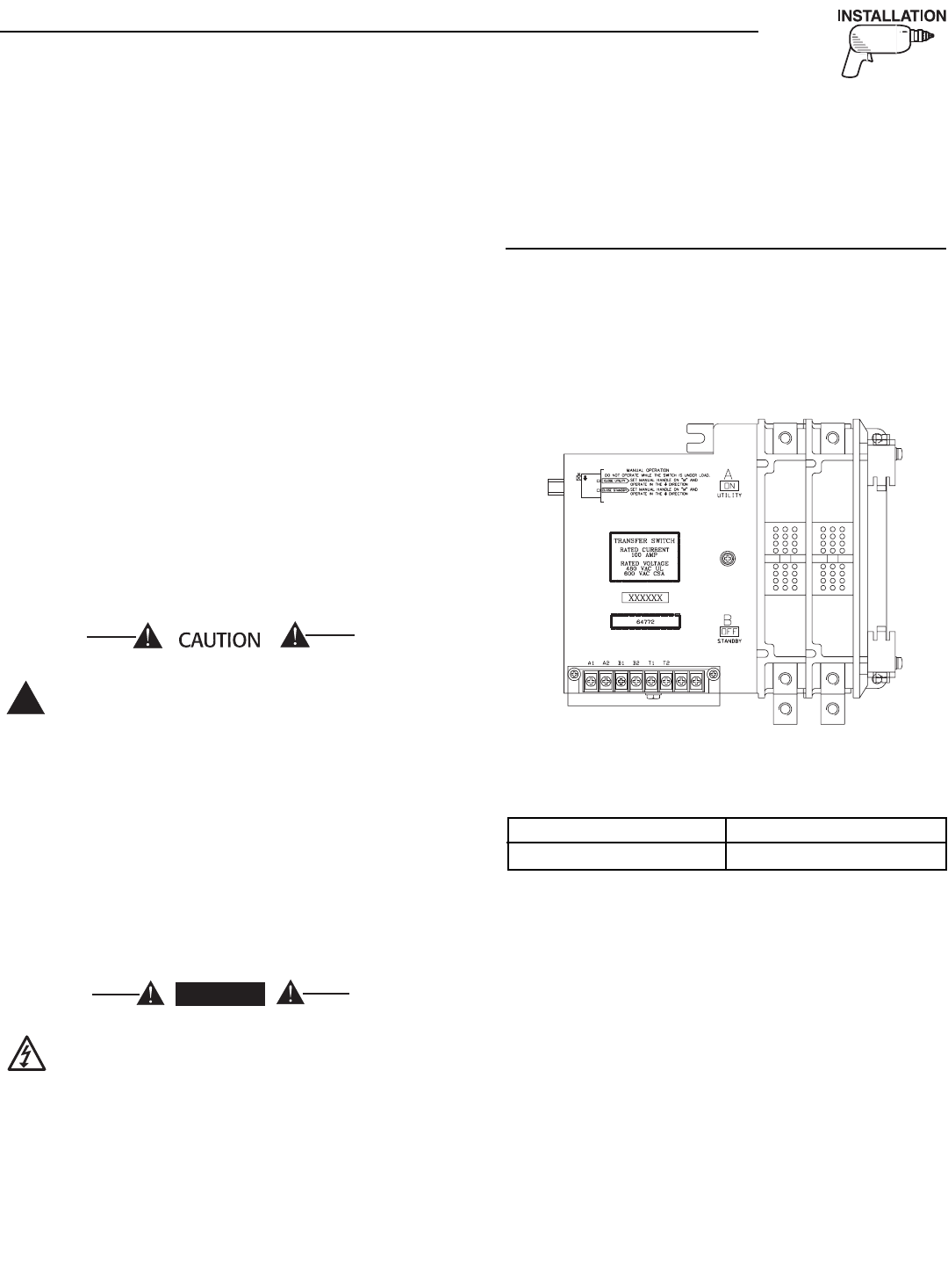
2.4.1 2-POLE MECHANISM
These switches (Figure 2.1) are used with a single
phase system, when the single phase NEUTRAL line
is to be connected to a Neutral Lug and is not to be
switched.
Figure 2.1 — Typical 2-Pole Transfer Mechanism
(100 Amp Shown)
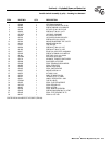
Solderless, screw-type terminal lugs are standard.
The conductor size range is as follows:
Conductor sizes must be adequate to handle the
maximum current to which they will be subjected;
based on the 75°C column of tables, charts, etc. used
to size conductors. The installation must comply fully
with all applicable codes, standards and regulations.
Before connecting wiring cables to terminals, remove
any surface oxides from the cable ends with a wire
brush. All power cables should enter the switch next
to transfer mechanism terminals. If ALUMINUM
conductors are used, apply corrosion inhibitor to
conductors. Tighten terminal lugs to the torque
values as noted on the decal located on the inside of
the door. After tightening terminal lugs, carefully wipe
away any excess corrosion inhibitor.
All power cables should enter the switch next to the
transfer mechanism terminals.
DANGER
!
Section 2 — Installation
Generac GTS “W” Type Transfer Switch
Switch Rating Wire Range
200A #4-400 MCM