


6 Generac
®
Power Systems, Inc.
3. When certain that UTILITY supply voltage is cor-
rect and compatible with transfer switch ratings,
turn OFF the UTILITY supply to the transfer
switch.
4. On the generator panel, set the AUTO-OFF-
MANUAL switch to MANUAL position. The gener-
ator should crank and start.
5. Let the generator stabilize and warm up at no-
load for at least five minutes.
6. Set the generator's main circuit breaker (CB1) to
its ON or CLOSED position.
PROCEED WITH CAUTION. GENERATOR OUT-
PUT VOLTAGE IS NOW BEING DELIVERED TO
TRANSFER SWITCH TERMINALS. CONTACT
WITH LIVE TERMINALS RESULTS IN EXTREMELY
DANGEROUS AND POSSIBLY FATAL ELECTRI-
CAL SHOCK.
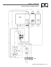
7. With an accurate AC voltmeter and frequency
meter, check the no-load, voltage and frequency.
Single-phase generator supply:
Measure across ATS terminal lugs E1 to E2; E1
to NEUTRAL and E2 to NEUTRAL.
a. Frequency ......................................60-62 Hz
b. Terminals E1 to E2 ........................240-246 VAC
c. Terminals E1 to NEUTRAL ............120-123 VAC
d. Terminals E2 to NEUTRAL ............120-123 VAC
Three-phase generator supply:
Measure across ATS terminal lugs E1 to E2, E2
to E3 and E1 to E3.
Measure across ATS terminal lugs E1 to NEU-
TRAL, E2 to NEUTRAL and E3 to NEUTRAL.
a. Frequency ......................................60-62 Hz
b. Terminals E1-E2, E2-E3, E1-E3 ....208-212 VAC
c. Terminals E1-N, E2-N, E3-N ..........120-122 VAC
It will also be necessary to verify that the phase rota-
tion of the utility matches the phase rotation of the
generator. This can be done by using a phase rotation
indicator.
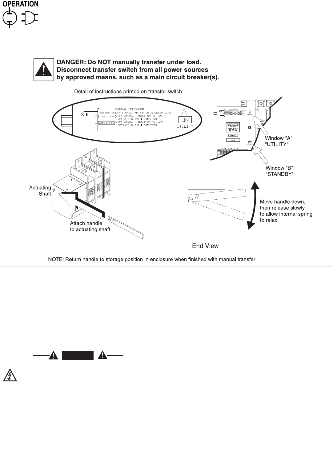
DANGER
Section 3 — Operation
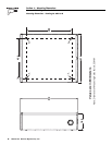
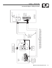
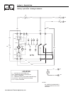
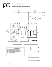
Generac GTS “W” Type Transfer Switch
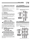
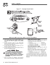
Figure 3.1 — Actuating Transfer Switch