


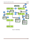

Integrated L-Band Up/Dn Converter LT3600 CG-1309
Page 12
SECTION 2 Installation
2.0 INTRODUCTION
This section defines the installation require-
ments by which the Integrated L-Band Up/Dn
Converter will meet the published
specifications.
2.1 UNPACKING AND INSPECTION
Remove the unit from its shipping container
and inspect for any damage sustained during
shipment. Save the packing material for
reshipment back to the factory or to another
site. Report any damage to the shipping
forwarder in accordance with required
procedures.
2.2 INSTALLATION REQUIREMENTS
The LT-3600 is designed for mounting in a
standard EIA 19-inch rack. The unit must be
supported on the sides and space must be
allowed at the side of the unit to permit the
flow of cooling air. The unit should be installed
in an environment that is within the environ-
mental envelope described in Table 1-1.
Primary power must be made available that is
within the specified limits.
2.3 MECHANICAL INSTALLATION
The chassis is equipped with threaded inserts
on either side for the installation of slides.
Slides are not provided with the unit. The front
panel is equipped with slots to accommodate
user-supplied retaining screws.
C
C
A
A
U
U
T
T
I
I
O
O
N
N
MOUNTING THE UNIT BY ONLY THE
FRONT PANEL WILL CAUSE EXTENSIVE
DAMAGE.
2.4 ELECTRICAL CONNECTIONS
All electrical connections are made to the rear
panel of the unit. The following describes the
rear panel connectors and its interface
requirements. The chassis ground is a #10-32
lug on the back panel.
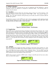
2.4.1 Power Input
This connector is an IEC 320-C14 male and
will accept any compatible mating connector.
The power cord supplied as standard with the
unit is equipped with a NEMA 5-15P male
plug at the opposite end and is compatible with
most 115 VAC supplies. The unit is manufact-
ured with a Universal Input Power supply that
will accept voltages in the range of 115 or 230
+/-15% VAC.
C
C
A
A
U
U
T
T
I
I
O
O
N
N
DAMAGE MAY RESULT IF THE INCORRECT
VOLTAGE IS APPLIED TO THE UNIT.
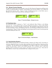
2.4.2 L-Band Output (J10)
This connector is selectable as an SMA or N-
Type female. The mate (not supplied) should
be compatible with the 50-ohm coax used to
connect to the system.
C
C
A
A
U
U
T
T
I
I
O
O
N
N
DC OUTPUT CURRENT MAY BE PRESENT
ON J4 AND J10 DEPENDING ON POWER
OPTIONS SUPPLIED FOR THE SSPB AND
LNB.
2.4.3 IF Input (J9)
This connector is a BNC female. The male
mate (not supplied) should be compatible with
the 50-ohm coax used to connect to the system.
2.4.4 IF Output (J3)
This connector is a BNC female. The male
mate (not supplied) should be compatible with
the 50-ohm coax used to connect to the system.
2.4.5 L-Band Input (J4)
This connector is selectable as an SMA or N-
Type female. The male mate (not supplied)
should be compatible with the 50-ohm coax
used to connect to the system.