


2
Planning Your Installation:
1. Determine the appliances, circuits or equipment you want to operate with generator power during a power outage, such as:
• Furnace
• TV / Radio
• Refrigerator
• Cordless Telephone
• Freezer
• Garage Door Opener
• Microwave Oven
• Water Heater
• Well Pump
• Security System
• Sump Pump
• Computer, Fax and Printer
• Lighting
• Range
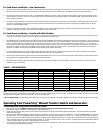
2. Determine the amps required for each appliance using the circuit breaker rating in the load center. No appliance should have an amperage rating that exceeds
the “GENERATOR MAIN” rating in the transfer switch. The total amperage of all circuits can exceed the generator rating, but not all circuits will be able to be
used concurrently.
3. Assign the circuit # in the load center and in the manual transfer switch, matching the size of the circuit breaker in the load center to the circuit breaker in the
transfer switch. Once you’ve determined which circuits you want to connect and the appropriate amperage, you will be ready to begin installing the manual
transfer switch.
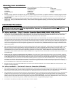
Installation Procedure:
IMPORTANT: Please read this entire procedure before beginning installation. WARNING: For SAFETY, turn OFF the MAIN
circuit breaker in the load center BEFORE starting installation. Remember, the wiring ahead of the MAIN is still HOT, even
when the main circuit breaker is off.
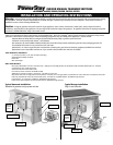
For Surface- Installation – “Plug-in” Generator Connection (Models 200660, 300660, 301060, 501210):
1. Transfer switch can be installed on either the left or right side of the main load center. Transfer switch is provided with 21-1/2” of flexible conduit. The connection to the
main load center, using the provided wire harness, must be made through one of the three (3) knockouts (KO’s) provided in the bottom or lower sides of the manual
transfer switch. The wire harness should enter the main load center in one of the bottom or lower side knockouts.
2.
Remove the cover of the main load center and the transfer switch. The conduit may be cut to a convenient length. Glue connectors on ends with PVC cement. After
attaching the flexible conduit to both boxes through the KOs, hold the transfer switch away from the load center against the wall on which it is to be mounted and mark
the keyholes on the wall for the anchoring screws. Be sure NOT to stress the flexible conduit, as it will break. [
NOTE: The blue Electrical Non-Metallic Tubing (ENT) is UL
Listed and recognized by the National Electrical Code (NEC). However, it generally cannot be used in buildings that exceed (3) floors above grade. While the NEC does
allow its use for this application, local codes and inspectors may prohibit its use. If this situation exists, call 888-GEN-TRAN to request a length of flexible metal conduit
(FMC) to use in its place.]
3. After mounting the transfer switch to the wall, you are ready to terminate the wires in the manual transfer switch. Fish the bundle of wires provided through the conduit.
Strip each wire in the wire harness approximately 5/8” and insert and tighten the wires to the correspondingly marked circuit breakers in the transfer switch. As you
attach each marked wire to the circuit breaker, write on the label on the cover of the transfer switch with the appliance on that circuit per the planning worksheet. The
unmarked BLACK wires in the harness are inserted into the Utility 2-pole breaker in the transfer switch. Attach the WHITE wire to the insulated neutral bar located
between the two meters inside the transfer switch, and attach the GREEN wire to the ground bar located in the lower left corner of the transfer switch. Reinstall the cover
to the transfer switch.
4. RECHECK TO BE SURE THE MAIN CIRCUIT BREAKER HAS BEEN TURNED OFF. The wires from the harness entering the load center can now be terminated. Remove the
wires of the appliances/loads that have been assigned to circuits in the transfer switch from the breakers in the load center. Cut the harness wires to a convenient length
and strip off approximately 5/8” and connect with the provided wire connectors (see wire connector chart) using the appropriate labeled wire from the transfer switch.
The unmarked BLACK wires in the harness are to be inserted into the NEW 2 pole breaker (as required in the Other Items Needed section). Remove two adjacent single
pole breakers from which the appliance/load wires were removed. The 2-pole breaker should be located in a bus bar location where two adjacent full
size single pole
circuit breakers were removed. Terminate the WHITE and GREEN wire in the harness in an open position in the Neutral and Ground bars respectively. If there is no separate ground
bar, insert the GREEN wire into an open position in the NEUTRAL bar, and tighten.
5. Reinstall the load center cover, and turn ON the MAIN breaker. Then turn ON ALL circuit breakers in both boxes. Turn on the UTILITY MAIN in the manual transfer switch. Check
that power is restored to all appliances.
For Surface Installation – “Hard-wired” Generator Connection (All Models):
1. After removing the cover from the transfer switch and before attaching the harness, remove the three screws that secure the power inlet to the top of the transfer switch. Pull the
power inlet out of the transfer switch, and loosen the four screws that secure the wires in the power inlet. Discard the power inlet. Secure the provided cover over the hole where
the power inlet was removed using the three screws securing the power inlet. (Model 601210 does not have a power inlet, so the cover is attached at factory.)
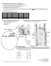
2. After attaching the harness and securing the transfer switch to the wall as described in STEPS 1 & 2 in the above section, the wiring to the generator can be done. This wiring should
only be done through one of the four KO’s on the top or upper ends of the transfer switch. The four wires removed from the power inlet should be connected together with the
appropriate wires coming from the generator using installer provided wire connectors. Notes on Model 601210: The current transformers (CTs) on this unit are “floating” and
therefore, installer must pass the hot leads from the incoming generator through the hole in the CT before inserting the wire into the “GEN MAIN” breaker. There is one CT per pole.
Install ground wire into unused hole in the ground bar, and install neutral wire into neutral bar. See Typical Hardwiring Diagram on Page 4.
3. The remainder of the installation, as described in STEPS 3, 4 & 5 above, can now be completed.