


3
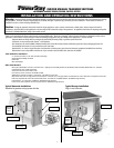
For Flush-Mount Installation – New Construction:
1. The transfer switch should be installed at the same time as the main load center in adjacent stud openings in the wall. Remove the six screws that secure the interior assembly of
the transfer switch to the switch enclosure. Remove the power inlet as described STEP 1 of in the “Surface Mount – Hardwiring” section above, except model 601210.
2. The width of the transfer switch enclosure is 14.25”; it should fit between standard 16” wall studs. Slots on the sides of the box allow the enclosure to be mounted to the studs.
Install the enclosure with nails or screws; be sure the front edge of the box extends forward to be flush with the thickness of the finished drywall. Adjustment is difficult once the
interior assembly is reinstalled.
3. The harness is installed by drilling a 2 1/8” diameter hole in the stud between the load center and the transfer switch. The exact location is determined by which KO’s in each box
are selected. The ideal location is the lower side corner of the load center and the bottom KO on the transfer switch. After removing the KO’s and drilling the hole, cement the
connectors and install the flexible conduit.
4. After the walls have been finished and painted (if applicable), reinstall the interior assembly of the transfer switch and complete the wiring as described in STEP 2 of “Surface
Installation – Hardwired” and STEPS 3, 4 & 5 in the “Surface Installation – Plug-In” section above.
For Flush-Mount Installation – Retrofit with Walls Finished:
1. Remove the cover of the main load center. Ensure that there are no wires going thru the side of the load center into the space where you want to mount the transfer switch. Use a
“stud finder” to determine if you have at least 14.25” between the studs to mount the transfer switch.
2. After determining where to install the transfer switch (keep in mind the length and flexibility of the conduit provided and where the generator wires will enter), remove the cover, the
power inlet and the six screws that secure the interior of the transfer switch as described in STEP 1 of the “Surface Installation – Hardwired” section above. Hold the transfer switch
enclosure in the desired position on the wall and mark the exact dimensions of the box. Set the enclosure aside and cut the hole in the drywall. Remove a 1” or 1-¼” KO in the
lower side of the load center. Drill a pilot hole through the stud in the center of the KO removed. Then, reach down inside the wall and drill a 2 1/8” diameter hole in the stud using
the pilot hole as a guide. Assuming you are mounting the transfer switch above the bottom corner of the load center, remove the bottom KO in the transfer switch, cement the
connectors on the flexible conduit, and install the flexible conduit and fasten to both cabinets with locknuts.
3. It is recommended that only the four KO’s in the upper portion of the transfer switch enclosure be used for entry of the generator wires. If this is impractical in your installation,
other holes may be drilled on the top, bottom or back to accommodate the incoming wires from the generator.
4. Insert the transfer switch enclosure box into the hole in the drywall and install with nails or screws; be sure the front edge of the box extends forward to be flush with the thickness
of the finished drywall. Adjustment is difficult once the interior assembly is reinstalled.
5. Reinstall the interior assembly of the transfer switch and complete the wiring as described in STEP 2 of “Surface Installation – Hardwired” and STEPS 3,4 and 5 in the “Surface
Installation – Plug-In” section above.
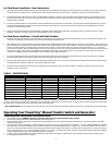
TABLE 1 - SPECIFICATIONS:
MODEL # 200660 300660** 301060 501210 601210
UTILITY MAIN breaker, Incl. 60 Amp 60 Amp 60 Amp 100 Amp 100 Amp
GEN MAIN breaker, included 20 Amp 20 Amp 30 Amp 50 Amp 60 Amp
Max Load per Circuit As marked As marked As marked As marked As marked
Max Load Combined 20 Amp 30 Amp 30 Amp 50 Amp 60 Amp
Max Watts @ 250 Volt 5000 N/A 7500 12,500 15,000
Max Watts @ 125 Volt 5000 3750 7500 12,500 15,000
Max 1-pole Circuits * 16 16 16 16 16
Max 2-pole Circuits * 8 0 8 8 8
NEMA Config. of Inlet L14-20 L5-30 L14-30 CS6375 N/A
Min. gauge Cord Size 12/4 wire 10/3 wire 10/4 wire 6/4 wire none
*Note: If Ground Fault Circuit Interrupters (GFCI) circuit breakers, Arc Fault Circuit Interrupters, or Surge Protector Circuit Breakers were used as the branch circuit protector in the main
load center, they MUST be used in the transfer switch. Because these circuit breakers typically take up more than one space, the overall maximum number of circuits may be reduced from
the number shown. Contact Gen/Tran for more information on these circuit breaker types.
**Note on Model 300660: This unit is designed and rated for 125 volt loads only; and single pole circuit breakers should be used in this unit. Total load must not exceed 3750 watts.
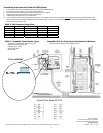
Operating Your PowerStay
®
Manual Transfer Switch and Generator:
Transferring from Utility Power to Generator Power:
1. Move generator outdoors. WARNING: Operating a generator indoors or in a garage could result in injury or death.
2. Insert the male connector of the Power Cord into the correct outlet on the generator.
3. Plug in the female connector of the Power Cord to the Power Inlet Box OR the inlet on the top of the PowerStay Manual Transfer Switch. Turn all circuit breakers in the transfer
switch to their OFF position.
4. Start the generator outdoors, following the procedures described in the generator’s owner’s manual furnished by the manufacturer. Turn on the GENERATOR MAIN circuit breaker in
the transfer switch. Turn ON circuit breakers in the manual transfer switch one at a time alternating from phase “A” and phase “B”. If meters are provided in your unit, watch as
you turn on successive circuits that the meters do not continuously exceed the maximum wattage of the generator. It may be necessary to alternate the use of larger loads (furnace
motors, well pumps, freezers, etc.) to avoid overloading the generator. Try to “balance” the loads on each “phase” (A and B). To promote generator life, loads should be balanced
so that the wattage reading on each meter is within about 1000 watts of the other.
5. Test your circuits by using the wattmeters or determine wattage from that shown on each appliance. Make a note of any excessive loads which must be removed from a given
circuit during generator operation in an emergency.