


22
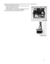
7. Re-plug cables to Control Module remove in step 2 and PowerPause connector to PowerPause Modules.
8. Re-install Control Module into transfer switch.
a. Line up Control Module to breaker bus stabs from where removed in step 1.
b. Hold at 30° angle, push onto bus stabs
c. Lower outside end flush with enclosure.
d. Slide Control Module ½” towards enclosure outside edge, lock into place.
e. Install (if required) circuit breaker opposite Control Module.
9. Route and dress wires in gutter of transfer switch enclosure.