


3
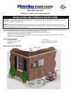
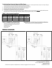
For “Hard-wired” Generator Connection: (Models R6010, R6020, R1020, R1220)
1. Follow steps 1 - 6 as described above.
2. Installer to determine size of conduit for bringing power from generator to the Power Center. KOs on bottom of Power Center should be
used, although alternate entry is adequate when necessary. Watertight hubs should be used above live breaker terminals. NOTE: If a 2” KO
is cut in the side of the Power Center enclosure, the dead front panel may need to be “notched” to clear the 2” fittings. The back of the KO
must be 3/8” from the rear of the enclosure.
3. Terminate wires from generator to “Generator Main” circuit breaker lugs on the Right side of the bus assembly. Terminate neutral and
ground wires into the appropriate bars provided.
4. Proceed with steps 7, 8 and 9 as described above.
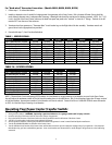
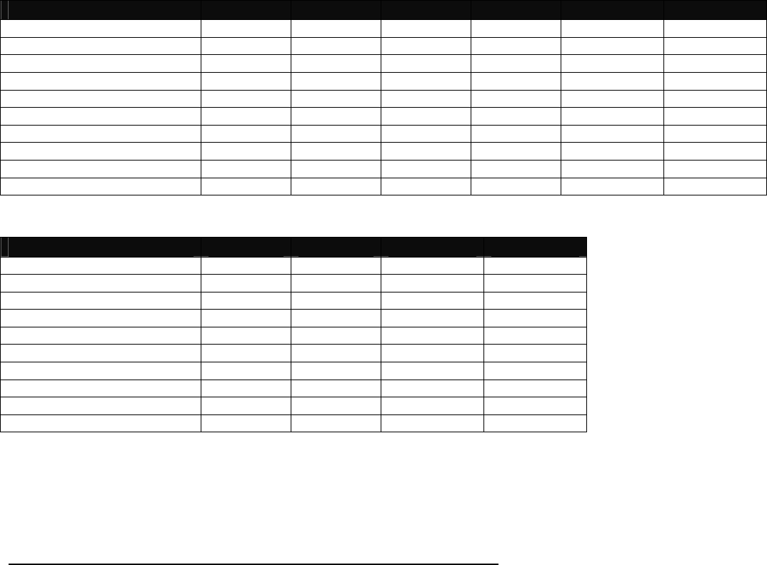
TABLE 1 - SPECIFICATIONS:
MODEL # R2060 R3060 R5010 R2020 R3020 R5020
UTILITY MAIN breaker, Included 60 Amp 60 Amp 100 Amp 200 Amp 200 Amp 200 Amp
GEN MAIN breaker, included 20 Amp 30 Amp 50 Amp 20 Amp 30 Amp 50 Amp
Max Load per Circuit As marked As marked As marked As marked As marked As marked
Max Load on Generator 20 Amp 30 Amp 50 Amp 20 Amp 30 Amp 50 Amp
Max Watts @ 250 Volt 5000 7500 12,500 5000 7500 12,500
Max Watts @ 125 Volt 5000 7500 12,500 5000 7500 12,500
Max 1-pole Circuits * 16 16 16 12 12 12
Max 2-pole Circuits * 8 8 8 6 6 6
NEMA Config. of Inlet L14-20 L14-30 CS6365 L14-20 L14-30 CS6365
Min. gauge Cord Size 12/4 wire 10/4 wire 6/4 wire 12/4 wire 10/4 wire 6/4 wire
TABLE 1A – SPECIFICATIONS:
MODEL # R6010 R6020 R1020 R1220
UTILITY MAIN breaker, Included 100 Amp 200 Amp 200 Amp 200 Amp
GEN MAIN breaker, included 60 Amp 60 Amp 100 Amp 125 Amp
Max Load per Circuit As marked As marked As marked As marked
Max Load on Generator 60 Amp 60 Amp 100 Amp 125 Amp
Max Watts @ 250 Volt 15,000 15,000 25,000 30,000
Max Watts @ 125 Volt 15,000 15,000 25,000 30,000
Max 1-pole Circuits * 16 12 12 12
Max 2-pole Circuits * 8 6 6 6
NEMA Config. of Inlet N/A N/A N/A N/A
Min. gauge Cord Size Hardwired Hardwired Hardwired Hardwired
NOTE: if Ground Fault Circuit Interrupting (GFCI) breakers, Arc-Fault breaker or surge protecting circuit breakers are used in the Power Center,
they will reduce the maximum number of circuits from the number shown in the table above. Also if circuit breakers larger than 50 amps are used
as sub-feed breakers, the maximum number of circuit breakers will also be reduced. Contact Gen/Tran at 1-888-GEN-TRAN for more information
on GFCI, Arc-Fault and Surge Protecting circuit breakers.
Operating Your Power Center Transfer Switch:
Transferring from Utility Power to Generator Power:
1. Move generator outdoors. WARNING: Operating a generator indoors or in a garage could result in injury or death.
2. Insert the male plug of the Power Cord into the correct outlet on the generator.
3. Plug in the female connector of the Power Cord to the inlet (if provided) located on the bottom of the Power Center.
4. Turn OFF all circuit breakers in the Power Center and Main load center.
5. Start the generator outdoors, following the procedures described in the generator’s owner’s manual furnished by the manufacturer.
6. Turn ON the GENERATOR MAIN circuit breaker in the Power Center.
7. Turn ON individual circuit breakers in the Power Center and the Main load center up to the continuous wattage rating of your generator. If the Generator
Main breaker trips, you have overloaded the generator. Some circuit breakers must be turned OFF to avoid damage to the generator or to the loads being
connected.