


Copyright © Gianni Industries, Inc. All Rights Reserved.
P-MU-EASIPROX Ver. B Published on 2008.02.12 Page: 2/ 4
III. The indicator signal chart:
Signal Condition
Yellow Power on, Stand-by
Green Lock relay active
User Signals
Red Invalid Card
Yellow、Green Flashing
The memory is empty
Green Flashing Into the ADD CARDS MODE
Red Flashing Into the DELETE CARDS MODE
Yellow、Red Flashing
Into the CLEAR MEMORY MODE
Yellow Flashing Into the TIME ADJUST MODE
Programming
Signals
Green Blinking Clearing Memory
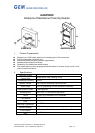
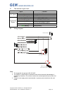
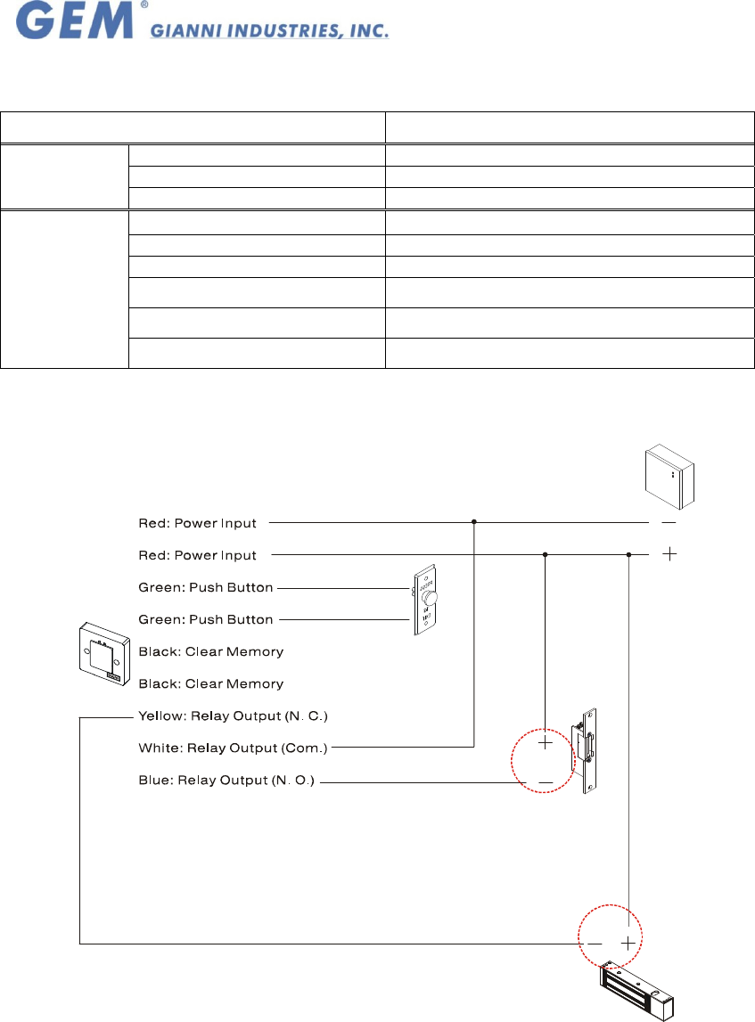
IV. Wiring diagram:
Push Button
(N.O./Com.)
Power Supply
Electric Strike
(Fail-Secure Typical)
Electric magnet
(Fail-safe Typical)
Note:
1. The suggested wire gauge is #22~26 AWG.
2. The varistor or diode must be connected across the lock terminal (electromagnet...)
operated by the device. The vartistor controls the overload produced by the strike coil
(EMP).
3. Using a Linear supply power recommended, to prevent power reduction at the card
reader.