


6BA
3-7
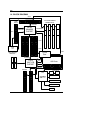
3.4. DRAM INSTALLATION
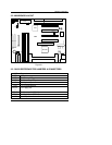
The main board can be installed with 8 / 16 / 32 / 64 / 128 / 256 MB 168 pins
DIMM module DRAM. When system bus speed is set to 100MHz, 100MHz
SDRAM is required. The DRAM memory system on main board consists of
bank 0, 1, 2 & bank 3.
Since 168 pins DIMM module is 64 bits width, therefore 1 piece of DIMM
module may match a 64 bits system. The total memory size is 8 MB ~ 1 GB
SDRAM. The DRAM installation position refer to Figure 3.1, and notice the
Pin 1 of DIMM module must match with the Pin 1 of DIMM socket. Insert the
DRAM DIMM module into the DIMM socket at Vertical angle. If there is a
wrong direction of Pin 1, the DRAM DIMM module could not be inserted into
socket completely.
3.5. CPU SPEED SETUP
The system bus speed can be set to 66.6MHz or 100MHz form the jumper
(JP8). The user can change the DIP SWITCH (SW) selection to set up the
CPU speed for different processors. The CPU speed must match with the
frequency RATIO and Front Side Bus (FSB) speed. It will cause system
hanging up if the frequency RATIO and FSB Speed do not match with the
CPU.
Set system speed to 66MHz: JP8 pin 1-2 short will cause system
always run at 66 MHz FSB (Front Side Bus).
Set system speed to 100MHz: JP8 all pins open will cause system
always run at 100MHz FSB.
Set system speed to Auto: JP8 pin 2-3 short will detect system
speed 66/100MHz FSB automatically.
JP8
3 2 1
JP8
3 2 1
JP8
3 2 1