


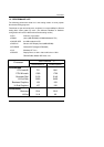


6EA
3-7
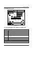
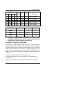
3.7. SPEAKER CONNECTOR INSTALLATION
There is a speaker in AT system for sound purpose. The 4 - Pins connector
SPK is used to connect speaker.
3.8. HARDWARE RESET SWITCH CONNECTOR INSTALLATION
The RESET switch on panel provides users with HARDWARE RESET function.
The system will do a cold start after the RESET switch is pushed and released
by user. The RESET switch is a 2 PIN connector and should be installed to
RST on main board.
3.9. POWER LED CONNECTOR INSTALLATION
System has power LED lamp on the panel of case. The power LED will light on
off or flash to indicate which step on the system. The connector should be
connected to PWR of main board in a correct direction.
3.10. IDE & ATAPI DEVICE INSTALLATION
There are two-Enhanced PCI IDE ports (IDE1, IDE2) on board, which following
ATAPI standard SPEC. Any one IDE port can connected to two ATAPI devices
(IDE Hard Disk, CD-ROM & Tape Driver), so total four ATAPI devices can exist
in a system. The HD is the active LED port for ATAPI devices.
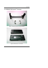
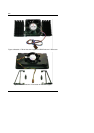
3.11. PERIPHERAL DEVICE INSTALLATION
After the I/O device installation and jumpers setup, the mainboard can be
mounted into the case and fixed by screw. To complete the mainboard
installation, the peripheral device could be installed now. The basic system
needs a display interface card. If the PCI - Bus device is to be installed in the
system, any one of four PCI - Bus slots can be used.
3.12. KEYBOARD & PS/2 MOUSE INSTALLATION
The main board supports PS/2 Mouse (J7). The BIOS will auto detect whether
the PS/2 Mouse is installed or not & assign IRQ12 for PS/2 Mouse port if it is
installed. After installing the peripheral device, the user should check
everything again, and prepare to power-on the system.