


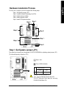
- 15 - Hardware Installation Process
English
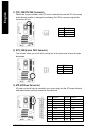
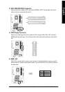
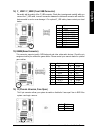
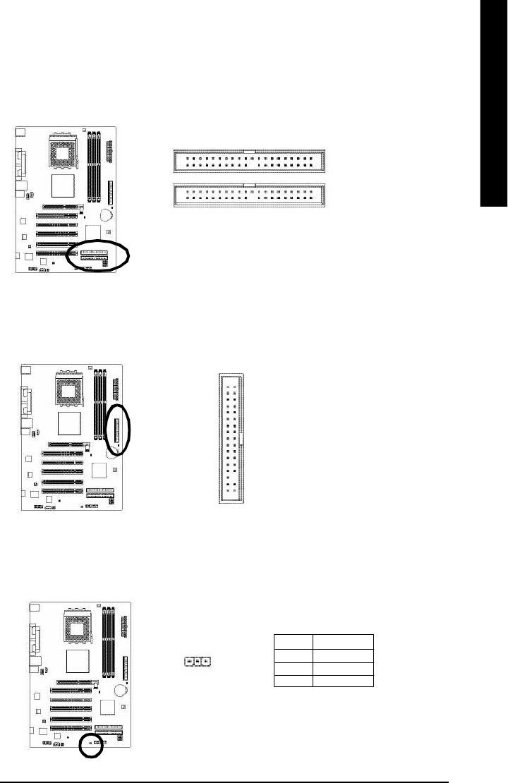
4) IDE1/ IDE2(IDE1/IDE2 Connector)
Please connect first harddisk to IDE1 and connect CDROM to IDE2. The red stripe of the ribbon
cable must be the same side with the Pin1.
IDE1
IDE2
2
40
1
39
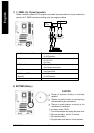
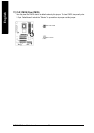
5) FDD (Floppy Connector)
Please connect the floppy drive ribbon cables to FDD. It supports 360K,720K,1.2M,1.44M and
2.88Mbytes floppy disk types. The red stripe of the ribbon cable must be the same side with the
Pin1.
1
34
2
33
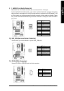
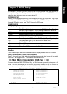
6) PWR_LED
PWR_LED is connect with the system power indicator to indicate whether the system is on/off. It
will blink when the system enters suspend mode. If you use dual color LED, power LED will turn
to another color.
1
Pin No. Definition
1 MPD+
2 MPD-
3 MPD-