- 13 - Hardware Installation Process
English
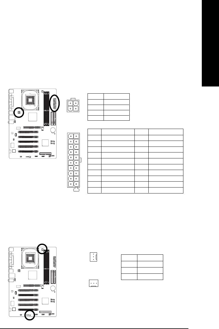
1/2) ATX_12V / ATX (Power Connector)
With the use of the power connector, the power supply can supply enough stable power to all the
components on the motherboard. Before connecting the power connector, please make sure that
all components and devices are properly installed. Align the power connector with its proper
location on the motherboard and connect tightly. The ATX_12V power connector mainly supplies
power to the CPU. If the ATX_12V power connector is not connected, the system will not start.
Caution! Please use a power supply that is able to handle the system voltage requirements. It is
recommended that a power supply that can withstand high power consumption be used (300W or
greater). If a power supply is used that does not provide the required power, the result can lead
to an unstable system or a system that is unable to start.
3/4) CPU_FAN / SYS_FAN (Cooler Fan Power Connector)
The cooler fan power connector supplies a +12V power voltage via a 3-pin power connector and
possesses a foolproof connection design. Most coolers are designed with color-coded power
connector wires. A red power connector wire indicates a positive connection and requires a +12V
power voltage. The black connector wire is the ground wire (GND).
Caution!
Please remember to connect the power to the CPU fan to prevent CPU overheating and failure.
Pin No. Definition
1 GND
2 +12V
3 Sense
1
1
CPU_FAN
SYS_FAN
Pin No. Definition
1 GND
2 GND
3 +12V
4 +12V
Pin No. Definition
1 3.3V
2 3.3V
3 GND
4 VCC
5 GND
6 VCC
7 GND
8 Power Good
9 5V SB (stand by +5V)
10 +12V
Pin No. Definition
11 3.3V
12 -12V
13 GND
14 PS_ON(soft on/off)
15 GND
16 GND
17 GND
18 -5V
19 VCC
20 VCC
1
20
10
11
12
34


