


GA-7N400S(-L) Motherboard - 12 -
English
The heatsink may adhere to the CPU as a result of hardening of the heatsink paste. To prevent
such an occurrence, it is suggested that either thermal tape rather than heat sink paste be used for
heat dissipation or using extreme care when removing the heatsink.
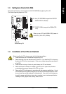
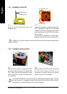
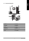
1-4-2 Installation of the Heatsink
Fig. 1
Before installing the heat sink, please first add an
even layer of heat sink paste on the surface of the
CPU. Install all the heat sink components (Please
refer to the heat sink manual for detailed installa-
tion instructions).
Fig. 2
Please connect the heat sink power connector to
the CPU_FAN connector located on the
motherboard so that the heat sink can properly
function to prevent CPU overheating.
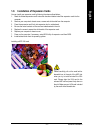
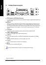
Position lever at a
90-degree angle
Fig. 1
Gently lift the CPU socket lever and up to a
90-degree angle.
Fig. 2
A gold-colored triangle is marked one edge of the
CPU. Please align this edge with the socket edge
closest to the CPU lever. Gently place the CPU into
position making sure that the CPU pins fit perfectly
into their holes.
Once the CPU is positioned into it socket, gently
press the metal lever back into its original position.
1-4-1 Installation of the CPU
Pin 1(indented corner)
A Socket A CPU has two indented corners and these corners must be properly positioned during
installation.
indented corner