


GA-8I915ME Series Motherboard - 26 -
English
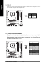
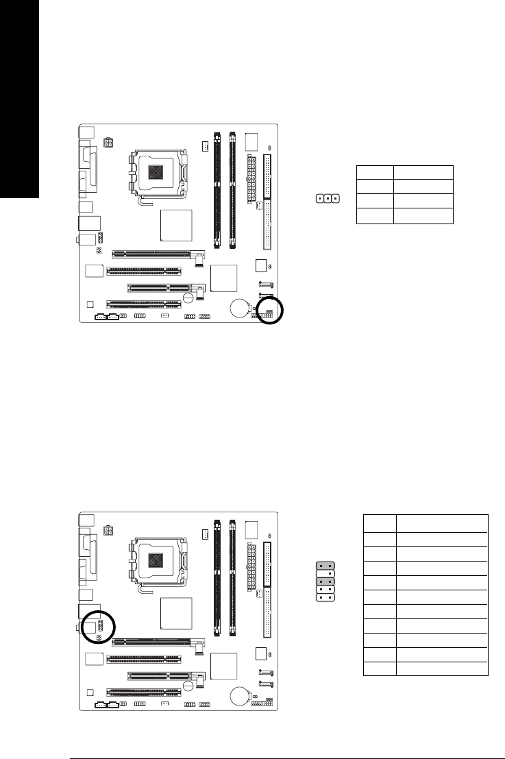
1
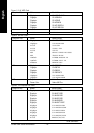
Pin No. Definition
1 MPD+
2 MPD-
3 MPD-
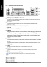
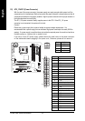
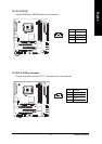
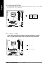
10) PWR_LED
PWR_LED is connect with the system power indicator to indicate whether the system is on/off. It
will blink when the system enters suspend mode.
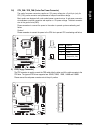
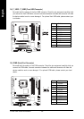
11) F_AUDIO (Front Audio Connector)
Please make sure the pin assignments on the cable are the same as the pin assignments of the
F_AUDIO connector on the motherboard. To find out if the chassis you are buying support front
audio panel connector, please contact your dealer. If you want to use "Front Audio" connector, you
must remove the jumpers on pin 5-6, 9-10.
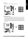
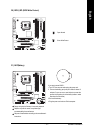
12
910
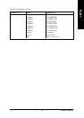
Pin No. Definition
1 MIC
2 GND
3 MIC_BIAS
4 POWER
5 FrontAudio(R)
6 Rear Audio (R)/ Return R
7NC
8 No Pin
9 FrontAudio (L)
10 Rear Audio (L)/ Return L