


GA-K8NMF-9 Motherboard - 22 -
English
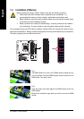
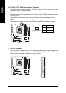
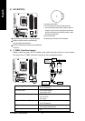
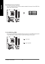
8) BAT (BATTERY)
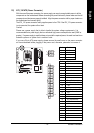
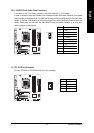
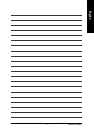
9) F_PANEL (Front Panel Jumper)
Please connect the power LED, PC speaker, reset switch and power switch etc. of your chassis
front panel to the F_PANEL connector according to the pin assignment below.
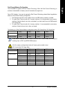
MSG (Message LED/Power/Sleep LED) Pin 1: LED anode(+)
Pin 2: LED cathode(-)
PW (Power Switch) Open: Normal Operation
Close: Power On/Off
SPEAK (Speaker Connector) Pin 1: VCC(+)
Pin 2- Pin 3: NC
Pin 4: Data(-)
HD (IDE Hard Disk Active LED) Pin 1: LED anode(+)
Pin 2: LED cathode(-)
RES (Reset Switch) Open: Normal Operation
Close: Reset Hardware System
NC NC
1
2
19
20
HD-
HD+
RES+
RES-
NC
SPEAK-
MSG-
MSG+
PW-
PW+
SPEAK+
Speaker Connector
IDE Hard Disk
Active LED
Message LED/
Power/
Sleep LED
Power
Switch
Reset Switch
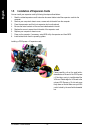
Danger of explosion if battery is incorrectly replaced.
Replace only with the same or equivalent type
recommended by the manufacturer.
Dispose of used batteries according to the manufacturer's
instructions.
If you want to erase CMOS...
1.Turn OFF the computer and unplug the power cord.
2. Take out the battery gently and put it aside for about 10
minutes (Or you can use a metal object to connect the
positive and negative pins in the battery holder to make
them short for one minute).
3.Re-install the battery.
4.Plug the power cord and turn ON the computer.