


- 28 -
English
GA-M55SLI-S4 Motherboard
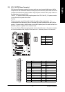
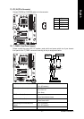
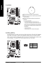
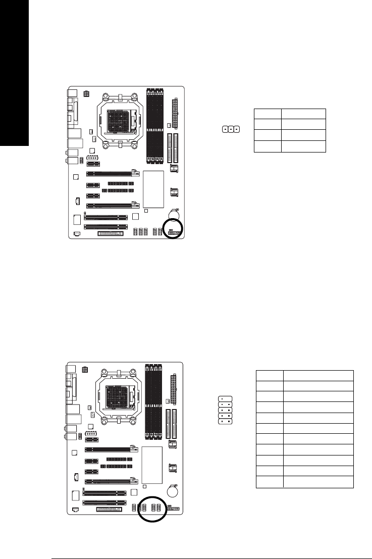
13) PWR_LED
The PWR_LED connector is connected with the system power indicator to indicate whether the
system is on/off. It will blink when the system enters suspend mode.
Pin No. Definition
1 MPD+
2 MPD-
3 MPD-
1
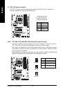
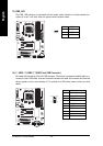
14) F_ USB1 / F_USB2 / F_USB3 (Front USB Connector)
Be careful with the polarity of the front USB connector. Check the pin assignment carefully while you
connect the front USB cable, incorrect connection between the cable and connector will make the
device unable to work or even damage it. For optional front USB cable, please contact your local
dealer.
Pin No. Definition
1 Power (5V)
2 Power (5V)
3 USB DX-
4 USB Dy-
5 USB DX+
6 USB Dy+
7 GND
8 GND
9 No Pin
10 NC
1
9
2
10