


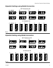

Determining Transceiver Dipswitch Settings
8 311002C
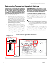
Determining Transceiver Dipswitch Settings
Each Transceiver is equipped with two, 4 - position dip-
switches labeled S1 and S2 representing the network ID
(S1) setting and the Transceiver ID (S2) setting. See
F
IG. 8. There is a possibility of (8) Network ID's and (8)
Transceiver ID's. The eight positions for each Network
ID and Transceiver ID are identified as A, B, C, D, E, F,
G, and H. See F
IG. 9 and FIG. 10.
• Network ID (S1): This is the RF identification
setting assigned to a Matrix installation. All com-
ponents in the system use this same Network
ID. For example, if one dealership is using Net-
work ID (A), the dealership across the street
would required Network ID (B) to avoid RF inter-
ference between the two systems.
• Transceiver ID (S2): This is the RF identifica-
tion setting assigned to a Matrix Transceiver(s).
Matrix system components are then assigned to
the Transceiver(s) ID's as desired for RF com-
munication. For example, If a system required
two Transceivers, some components would be
assigned to one Transceiver and other compo-
nents would be assigned to the second Trans-
ceiver using the Transceiver ID dipswitch.
Existing Matrix Facility - If the Transceiver is already
installed, two large letters should be visible on the out-
side of the box. The first letter represents the Network ID
and the second letter represents the Transceiver ID.
If no letters are present on the installed Transceiver, it
may be necessary to look inside the Transceiver box to
determine the dipswitch settings. First determine if an
RS232 or an RS422 connection is used and then refer
to F
IG. 9 and FIG. 10 to determine the Network ID and
Transceiver ID.
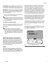
New Matrix Facility - the factory default setting for all
Transceivers is (AA). The first A refers to the Network ID
and the second A refers to the Transceiver ID. It does
not matter in a new installation if an RS232 or an RS
422 connection will be used at the time of installation.
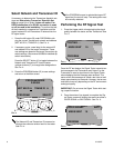
Testing can be completed while the Matrix system
is in use. The test messages sent by the RF Signal
Tester will be ignored by the PC that is connected
to the system.
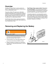
F
IG. 8
Network ID (S1)
Transceiver ID (S2)
12
3
4
S2
on
1
2
3
4
S1
o
n
All dipswitches in down
or off position.
All dipswitches
to right or off
position.
Transceiver Dipswitch Positions