


– 23 –
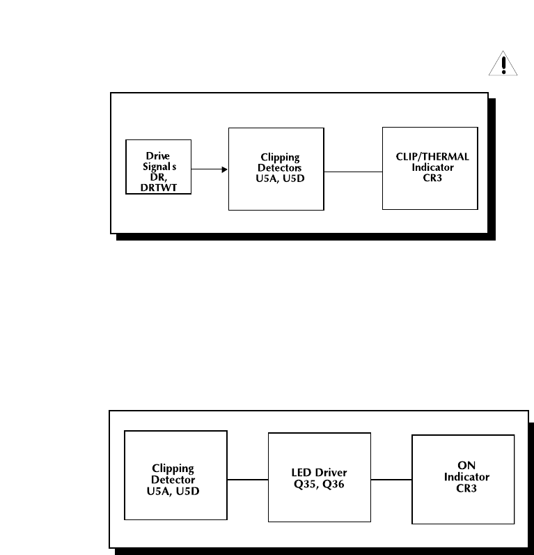
Clipping Indicator
The CLIP indicators are driven by the comparator U5A and U5D. The voltage divider R56, R57, and R51, R61
establishes the reference voltage for the Clipping detector at pin 7 of U5A and pin 9 of U5D. Excessive drive sig-
nal at pin 6 or pin 8 will trigger its comparator low and light the CLIP/THERMAL indicator red.
On Indicator
The bicolor LED, CR3, will remain green unless a THERMAL or CLIP condition is detected. The outputs of com-
parators U5A and U5D will be high, and Q35 will be off, allowing current to flow through the green LED of CR3
from ground to –17V.
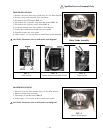
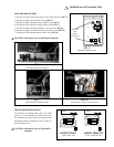
Qualified Service Personnel Only