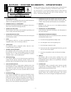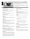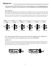
XLR Balanced Input
Check output from source for proper signal polarity
Pin 1 = GND
Pin 2 = (+)
Pin 3 = (–)
INPUT FROM
SOURCE
XLR Unbalanced Input
Connect (–) and GND (shield) terminals at both ends of cable to
prevent unstable amplifier operation
Pin 1 = GND
Pin 2 = (+)
Pin 3 = GND
INPUT FROM
SOURCE
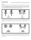
DETERMINING ACOUSTIC CENTER
Finding the “Acoustic Center” is accomplished by positioning the monitors so
coherent arrival of the transducers occurs at ear level. The Acoustic Center is
located 3 to 4 feet in front of the monitor, measuring perpendicularly from the
center point of the cabinet (midway between the woofer and tweeter). Our
tests have shown that a flat phase and frequency response occurs just above
and below the Acoustic Center with the minimum and maximum height
spanning between the tweeter dome and woofer dust cap.
– 6 –
XLR WIRING CONFIGURATIONS
Using the balanced XLR input is recommended for installations where long cable runs are used or when the potential for stray electromag-
netic fields from other wires exists. There is a balanced and unbalanced method in which the XLR inputs can be used. The first method is
an XLR Balanced Input using 3-conductor cable. The balanced signals carried on pins 2 and 3 are equal in amplitude and opposite in phase.
Pin 1 is the ground and shield. In this configuration, noise common on both phases of signal are effectively "canceled" out. The second
method is an XLR Unbalanced Input using 2-conductor cable with the signal carried in the center conductor and the ground carried on the
shield. Many popular mixers use unbalanced outputs and can be used with the XLR balanced input. However, in this type of configuration
we recommend using twisted pair cable or short cable length to prevent residual ground noise.
INPUT SWITCH
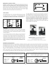
The unbalanced input uses a conventional RCA phone jack. Move
the input switch ON (-->) to use this jack. The balanced input jack
is an XLR plug. The XLR jack is connected according to the IEC and
AES standard. Move the input switch OFF (<--) to use this jack.
MOUNTING
The monitor may be mounted on a wall or ceiling, using suitable
mounting hardware. The base of the monitor includes mounting
inserts designed for use with “OmniMount Systems®” or equivalent
mounting products
1
.
If you mount the monitors to a wall or ceiling, you must take special
care to mount them securely to prevent them from falling and caus-
ing damage or injury. Make sure that the mounting hardware (fas-
teners and connectors) and the surface you are mounting to are each
capable of securely holding the monitor in place even if it is struck
or moved. Make sure the mounting hardware, fasteners, and con-
nectors are rated for an object at least as heavy and bulky as the
monitor.
Use good judgement and common sense throughout all phases of
the installation and use mounting techniques appropriate for the sur-
face you select. Use the mounting hardware according to the man-
ufacturer's recommendation and provide adequate reinforcement to
the monitors if needed. Do not mount the monitor only to drywall—
make sure the fasteners are secured to a stud, joist, or other structural
support. If appropriate, use a secondary support for added safety—a
properly installed safety cable provides an extra margin of safety and
can be installed out of sight easily.
Unbalanced
Input
Move input
switch
RIGHT
(-->) to use
RCA
connector
Balanced
Input
Move input
switch
LEFT (<--)
to use
XLR
connector
OmniMount Part #
100 WB / 100 WBX
OmniMount Part #
100 ST-MP / 100 STX-MP
1 “OmniMount Systems®” is a registered trademark of OmniMount
Systems, 1501 West 17th Street, Tempe, Arizona 85281-6255,
TEL (602) 829-8000 FAX (602) 756-9000.
OmniMount Systems is not affiliated with Hafler or Rockford Corporation.


