


2
1.2 Wiring the wall switch
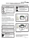
1.0 INSTALLATION INSTRUCTIONS
1.1 Determine Location
Determine the location for the wall switch. The selected
location should be in the same space as the gas fi replace.
Never place this unit in a separate room. The distance from
the fi replace to the switch may be up to 50 ft.
The switch should be mounted into a UL-listed electrical
junction box. The junction box should be dedicated to this
wall switch. Never install this wall switch into a junction box
that is shared with other electrical service or devices. If
possible, install this unit on an interior wall of the residence
at a recommended height of 5 ft from the fl ooring.
Should the switch be installed on an exterior wall, be
certain wall insulation is kept intact and not damaged or
dislodged during the installation of the electrical junction
box. For exterior wall installations, it is recommended that
the junction box be sealed with caulking material. This will
minimize heat loss through this location.
1. Install the control wire from the fi replace to the switch
location. Use caution not to stress the wire around tight
or sharp corners. Do not run the control wire adjacent
to existing or future phone, data, cable, or electrical
lines. The wire should not come into contact with any
part of the fi replace exterior with the exception of where
it exits the outer wrap. Feed the wire to the electrical
junction box and through a provided or approved strain
relief.
2. Strip outer casing back about 1-1/2 inch. Use caution
to avoid stripping inner wires.
3. Strip the white or yellow, red and green wire casings
back about 3/8 inch.
4. Use a screw driver to connect the red wire to the “R”
terminal, white or yellow wire to the “Y” terminal, and the
green wire to the “G” terminal. Do not overtighten.
5. Use the screws provided to mount the switch to the
electrical junction box right side up.
6. Install provided cover plate using the screws provided.
Do NOT use a substitute cover, even though it may
fi t.
NOTE: Wire supplied on the unit will be red, white and green.
Wire purchased separately will be red, yellow and green.
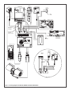
1.3 Installing the Control Box
1. Place control box into the base pan area of the fi replace.
Place unit as close to the louvers or decorative front as
possible and to either the left or right side.
2. Connect the red, yellow or white and green wires to the
R, Y and G labeled terminals on the control box.
3. Unplug the 8-pin wiring connector from the ignition
module box and plug it into the 8-pin connector slot on
the WSK control box.
4. Using the supplied wiring harness, plug the 8-pin
connector into the ignition module and the 6-pin
connector into the WSK control box.
5. Unplug the 3 volt adapter from the green IPI module and
plug it into the spade terminals of the black WSK control
box.
WARNING
Burn Risk.
Shock Risk.
•
Do not install the control box when fi re-
place is hot.
Do not plug control box in until all con-
nections are complete.
•
NOTE: The WSK200 and WSK210 have a built in timer
to turn the blower ON and OFF.
1.4 Installing the Blower (WSK200/210 Only)
1. See fi replace owner’s manual on fi replace for location
of the blower.
2. Plug the power cord from the blower into the receiver
box.
3. Disconnect and remove the temperature sensor switch
and speed control (rheostat) from the fi replace.