


-2-
598-1112-01
REPLACEMENT INSTALLATION WIRING
For replacing an existing transformer, follow step 2 above.
WARNING: Turn power off at fuse or circuit breaker before installing transformer.
1. Verify existing chime/bell system works correctly. If no sound is heard, see Troubleshooting
section for more information.
2. Check transformer power rating. This chime requires a minimum 16 Volt, 10 Watt transformer.
3. Remove cover from existing chime and disconnect wires from terminal screws. Using masking
tape or wire tags provided on packaging, label all wires (“F”-Front Push Button, “T”-Transformer,
“R”-Rear Push Button) as you remove them according to terminal markings.
4. Remove existing chime base from wall.
5. Route wires through wire entrance hole(s) in new chime base.
6. Mount chime base to wall using screws provided.
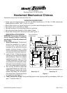
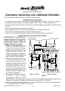
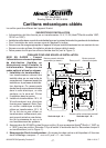
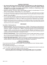
7. Connect wire “F” to the screw terminal marked “FRONT”. Connect wire “T” to screw terminal
marked “TRANS”. Connect wire “R” to screw terminal marked “REAR” (see Figure 1).
Note:
The
common connection may exist elsewhere in the original installation and may not be visible.
8. Place chime cover securely over base.
9. Restore power. Press push button(s) to test chime.
Note: For multiple mechanical chimes, use a 16 Volt, 15 Watt transformer.
HELPFUL HINTS
• Electrical work must be in accordance with national and local electrical codes. If in doubt,
consult a qualified electrician. Turn power off at fuse or circuit breaker before installing/
replacing transformer.
•Many chimes, bells, and buzzers are installed with a 10 Volt, 5 Watt transformer. This chime
requires a minimum 16 Volt, 10 Watt transformer.
• For replacement installation, identify and tag wires before removing them according to terminal
markings: “F”-Front Push Button, “R”-Rear Push Button, and “T”-Transformer.
• For new installations install #20 AWG bell wire in pairs from push button(s) and transformer to
chime. Do not pinch wire or damage its insulation. Heath
®
/Zenith accessory wire (No. 196C or
No. 199C) is available for chime installations.
• Clean wood, plastic, and metal parts with mild soap and warm water. Never use cleaners or
polishes. Never use any fluids on the mechanical chime mechanism.
5. Mount push button(s) to door frame(s). Run two No. 20 AWG bell wires from push button(s) to
the chime location. Strip away 1/2" of insulation from end of wires. Connect each wire to push
button(s) (see Figure 1).
Label Front Push Button Wires: Using masking tape or wire tags provided on packaging, label
one wire “F” and the other “C”.
Label Rear Push Button Wires: Using masking tape or wire tags provided on packaging, label
one wire “R” and the other “C”.
6. At the chime, pull all wires through wall cavity and out through a 1/2" hole in the wall board.
Route wires through wire entrance hole(s).
7. Mount chime base to wall using screws provided.
8. Strip away 1/2" of insulation from end of wires. Connect wire “F” to the screw terminal marked
“FRONT”. Connect wire “T” to screw terminal marked “TRANS”. Connect wire “R” to screw ter-
minal marked “REAR” (see Figure 1).
9. Twist together the wires labeled “C” and secure them with a UL approved wire nut.
10.Place chime cover securely over base.
11. Restore power. Press push button(s) to test chime.