


5
598-1208-00
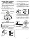
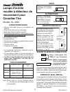
DUAL BRITE
®
ON-
TIM
E
TE
ST
1 5 10 MIN
OFF 3
6
DUSK
T
O
DAWN
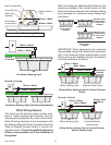
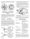
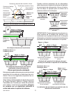
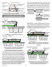
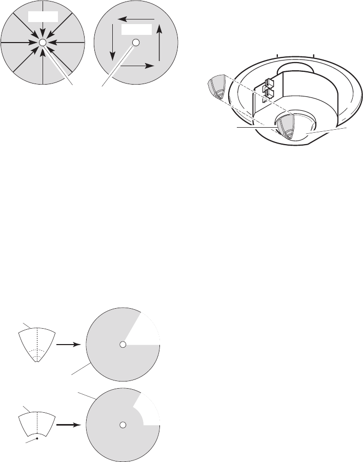
Least Sensitive Most Sensitive
The sensor is less sensitive to motion directly
towards it and more sensitive to motion across
coverage area.
Sensor
Motion
Motion
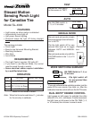
SPECIFICATIONS
Range ..........................Up to 30 ft. (9.1 m)
[varies with surrounding
temperature].
Sensing Angle ..............360°
Electrical Load .............Up to 100 Watt
Maximum Incandescent
(Up to 25 Watt Maxi-
mum each lampholder).
Bulb Type .....................Candelabra Base, Type
“B”, 25 Watt Maximum
Sensor Capacity...........Up to 200 Watt (1.7 A.)
Maximum
Power Requirements ...120 VAC, 60 Hz
Operating Modes .........TEST, AUTO/ACCENT,
and MANUAL MODE
ON-Timer .....................1, 5, 10 minutes
Dual Brite
®
Timer..........Off, 3, 6 Hrs, Dusk-to-
Dawn
DESA Specialty Products™ reserves the right to
discontinue products and to change specifications
at any time without incurring any obligation to incor-
porate new features in products previously sold.
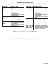
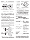
ADJUSTMENT OF COVERAGE
AREA
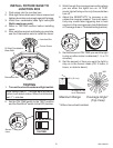
The sensor on this light fixture detects “motion” by
the movement of heat (body heat) across the
coverage area. However, following are examples
of objects that also produce heat and can cause the
sensor to false trigger:
• Pools of Water • Air Conditioners
• Dryer Vents • Fenced-In Animals
• Heating Vents • Automobile Traffic
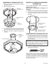
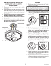
If you suspect that a heat source of this type is
falsely triggering the sensor and reducing the sen-
sitivity does not solve the problem, then a lens
shield (included) can be installed. The plastic lens
shield is divided into 6 sections. Each section will
reduce the coverage angle by 30 degrees. Also, the
tip of each section may be removed to change the
effective range of the sensor.
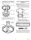
1. Break off the amount of lens shield needed to
block the desired area of coverage.
2. Cut desired amount of foam tape needed to
adhere the lens shield to the sensor lens.
3. Remove paper backing from one side of cut
foam tape and adhere foam tape to inside of
lens shield.
4. Remove paper backing from other side of cut
foam tape and adhere lens shield to sensor lens.
5. Retest to confirm that the sensor is no longer
false triggering.
Note:
To help determine amount of lens shield
required, apply small sections one at a time. Addi-
tional sections can be applied if necessary.
Lens Shield Sensor
Lens
Area
Blocked
Area
Blocked
Lens
Shield
Lens
Shield
Portion
Removed
Effective
Coverage Area
(Top View)