


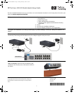

4. Install the Switch Hardware (Continued)
M-4 tap
screws
Ventilation
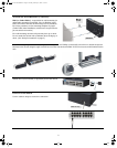
Wall (or Under-Table):
A special kit for wall-mounting (or
under-table mounting) is included. Use a #1 Phillips (cross-
head) screwdriver and the 20-mm M4 tap screws (included).
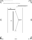
For screw positions, see the mounting template on page 4.
(Under-Table: After installation, a third screw
may be used to
prevent switch movement.)
For wall-mounting, the network ports may face up or down.
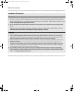
Do not
mount the switch with ventilation ducts facing up or
down. (See “Safety Precautions” on page 3.)
Rack Mounting: A speci
al rack-mounting kit is included. Use a #1 Phillips (cross-head) screwdriver to attach the special
brackets to the switch using the eight 8-mm M4 screws. Then use the four number 12-24 screws to secure the brackets to the
rack.
5. (Optional) Lock the Switch. Use a Kensington lock or
similar device (not included) to physically secure the switch.
6. Power On the Switch.
Use the cable tie strap to secure the connection.
Cable tie strap
7. Connect Network Cables.
2
QSG-1410-16G-Feb2010.fm Page 2 Thursday, February 25, 2010 7:45 PM