


14
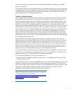
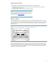
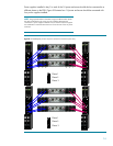
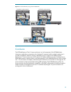
Power supplies installed in bay 2 in each of the 1U power enclosures should also be connected to a
different phase on the PDU. Figure 8 illustrates how 1U power enclosures should be connected with
four power supplies installed.
NOTE: The grayscale outlets on the PDU in Figure 8 indicate which phase
the outlet is attached to. The wires are color coded to distinguish the
connections to power supplies installed in bus A and bus B. Power supplies
are numbered in reverse because the view is from the rear of the 1U power
enclosure.
Figure 8. HP BladeSystem p-Class 1U power enclosures connections (rear view)
1
2
4
5 6 3
Phase 1
Phase 2
Phase 3
1
2
4
5 6 3
Phase 1
Phase 2
Phase 3