


Step 1: Removing the SFP transceiver
WARNING: To reduce the risk of injury from laser
radiation or damage to the equipment, observe the
following precautions:
■ Do not open any panels, operate controls, make
adjustments, or perform procedures to a laser device
other than those specified herein.
■ Do not stare into the laser beam when panels are
open.
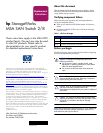
1. Press the release clip on the bottom of the cable connector
1 to remove the Fibre Channel cable.
2. Pull the transceiver out of the device by pulling up and out
on the plastic tab 2.
Note: Be sure to label each cable with the port it is being removed
from.
Figure 1: Removing the SFP transceiver
Caution: Touching the end of a fibre cable damages the
cable. Whenever a fibre cable is not connected, replace
the protective covers on the ends of the cables.
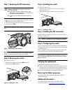
Step 2: Removing the switch
To remove the switch:
1. Slide the port-colored release latch 1 to the right.
2. Slide the switch 2 straight out.
Figure 2: Removing the switch
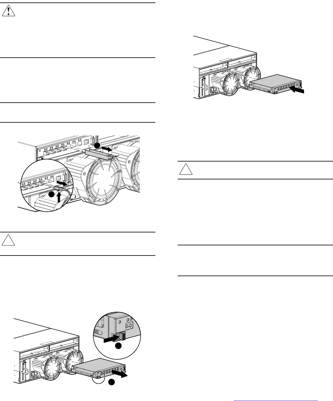
Step 3: Installing the switch
To install the new switch:
1. Slide the switch straight in. The release latch should
automatically close.
2. Make sure the release latch has closed and is secure.
Figure 3: Installing the switch
Step 4: Installing the SFP transceiver
Insert the SFP transceiver(s) into the new switch and replace
the Fibre Channel cable.
Caution: To reduce the risk of damage to the equipment,
do not use excessive force when inserting the transceiver.
Step 5: Configuring the switch
Do not connect the switch to a configured SAN without first
configuring the switch. Also verify that the replacement switch
is working properly.
Refer to chapters 3 and 4 in the HP StorageWorks MSA SAN
Switch 2/8 Installation Guide for detailed instructions.
Note: All switches in the fabric must be running the same version of
firmware. Refer to “Upgrading or Restoring the Switch Firmware,” in
the
HP StorageWorks MSA SAN Switch 2/8 Installation Guide
for
detailed instructions.
Verifying the replacement
After replacing the failed switch be sure that:
■ The service indicator LED is solid green. Unread error log
messages may cause the LED to remain flashing. Be sure
all error messages that have been responded to are deleted.
■ No new error messages are displayed on the LCD.
Returning the failed component
Please follow the return instructions provided in the new
component package.
Additional information
For additional information, refer to the MSA technical
documents web site at
http://www.hp.com/go/msa1000
.
2
1
15099
2
1
15069
15070