


Removal and Replacement Procedures
Maintenance and Service Guide 5–45
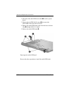
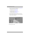
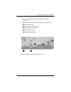
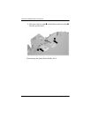
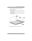
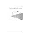
7. Position the notebook with the rear panel toward you.
8. Remove the following:
1 two HM5.0×9.0 screw locks on each side of the external
monitor connector
2 five PM2.0×8.0 screws that secure the system board to the
base enclosure
3 two PM2.0×8.0 screws that secure the heat sink module to
the base enclosure
Removing the System Board Screws and Screw Locks