


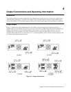

Output Connections and Operating Information48
available in the load leads for prolonged operation into a 5 A load during ac low line at high ambient temperature
conditions.
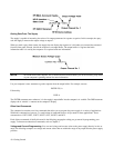
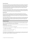
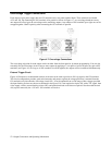
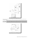
There is a similar stipulation for 80 W low voltage outputs at l0 A under the same conditions as above. See Figure 4-2A
for worst case voltages available at the output terminals.
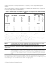
Table 4-1. Stranded Copper Wire Ampacity and Maximum Wire Lengths to Limit Load Lead Voltage
Drop
Ampacity Per Wire (Amps) Resistivity Max Length to Limit
Voltage to 1 V Per Lead
Wire Size 2 Wire Bundled 4 Wire Bundled 5 A 10 A 20 A
(AWG)
(Ω/ft)
(feet)
20 7.8 6.9 0.0102 20 10 5
18 14.5 12.8 0.0064 30 15 7.5
16 18.2 16.1 0.0040 50 25 12.5
14 29.3 25.9 0.0025 -- 40 20
12 37.6 33.2 0.0016 -- -- 30
(Cross Section
(Ω/m)
(meters)
Area in mm
2
)
0.5 7.8 6.9 0.0401 5 2.4 1.2
0.75 9.4 8.3 0.0267 7.4 3.8 1.8
1 12.7 11.2 0.0200 10 5 2.6
1.5 15.0 13.3 0.0137 14.6 7.2 3.6
2.5 23.5 20.8 0.0082 -- 12.2 6
Notes:
1. Ampacities for AWG wires are derived from MIL-W-5088B. Maximum ambient temp: 55°C. Maximum wire temp:
105°C.
2. Ampacities for metric wires are derived from IE Publication 335-1.
3. Ampacity of aluminum wire is approximately 84% of that listed for copper wire.
4. Because of wire inductance considerations, it is recommended that you keep your load leads twisted, tie wrapped, or
bundled together and less than 50 feet (14.7 meters) in length per lead.
5. See pages 47 & 48 for information on wire gauge considerations with capacitive loads.
NOTE To prevent tripping of the overvoltage circuit, pick a wire size sufficient to handle the FULL output
current of the unit no matter what the intended load current or current limit setting.
Table 4-1 lists the resistivity for various wire sizes and the maximum lengths to limit the voltage drop to 1.0 volts for
various currents.
NOTE The OVP circuit senses at the main output terminals and not on the sense leads. Thus, the voltage
sensed by the OVP circuit could be as much as 2 V higher than the voltage being regulated at the load.
Program the OVP trip voltage accordingly when using remote sensing. In addition, if the voltage drop
exceeds 1.5 V on either load lead, a protective circuit will fire the OVP circuit regardless of the OVP
setting.
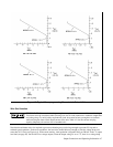
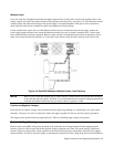
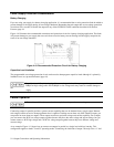
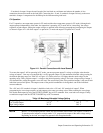
Load lead resistance is an important factor relating to the CV stability of the supply with remote sensing of capacitive
loads. If high capacitance loads are expected, you should not use wire gauges heavier than 12 to 14 AWG for long runs of
load lead. See Figure 1-4 for more information about stability with output capacitors.