


3 - Installation
24
Voltage Drops
The load wires must also be large enough to avoid excessive voltage drops due to the impedance of
the wires. In general, if the wires are heavy enough to carry the maximum short circuit current
without overheating, excessive voltage drops will not be a problem. The voltage drops across the
load wires should be limited to less than two volts. Refer to Table 3-2 to calculate the voltage drop
for some commonly used AWG copper wire.
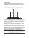
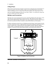
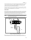
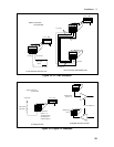
Multiple Load Connections
When the unit is in local sensing mode and you are connecting multiple loads to the output, connect
each load to the output terminals using separate load leads. This minimizes mutual coupling
effects and takes full advantage of the dc source's low output impedance. Each pair of wires should
be as short as possible and twisted or bundled to reduce lead inductance and noise pickup.
If cabling considerations require the use of distribution terminals that are located remotely from the
dc source, connect the dc source’s output terminals to the remote distribution terminals by a pair of
twisted or bundled wires. Connect each load to the distribution terminals separately. Remote
voltage sensing is recommended under these circumstances. Sense either at the remote distribution
terminals, or if one load is more sensitive than the others, sense directly at the critical load.
+S
+
-
-S
+ 240 VDC MAX TO
-
LOAD 3
LOAD 2
LOAD 1
twist or bundle
each pair
Figure 3-2. Multiple Load Connections
Remote Sense Connections