


Installation - 3
23
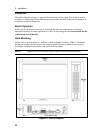
Input Connections
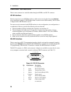
Connect the Power Cord
1. Unscrew the line fuse cap from the rear panel and verify that the fuse rating matches what is
specified on the FUSES label on the rear panel. Reinstall the fuse. (See table 3-1 for fuse part
numbers.)
2. Connect the power cord to the IEC 320 connector on the rear of the unit. If the wrong power
cord was shipped with your unit, contact your nearest HP Sales and Support Office (refer to
the list at the back of this guide) to obtain the correct cord.
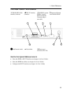
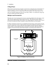
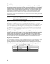
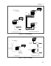
Output Connections
The output terminal block has connections for the + and − output, the + and − sense inputs, and an
earth ground terminal. The terminal block screws are 6-32 X 3/8 inch. Remove the safety cover by
inserting a flat bladed screwdriver in the opening on the left side of the cover and pushing the
locking tab to the left. This will release the cover.
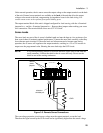
Optional front panel binding posts are available to connect load wires for bench operation. The
front panel binding posts are paralleled with the rear panel + and − connections. Before using the
front panel binding posts, make sure that the output terminals are jumpered for local sensing.
NOTE: Front panel binding posts are provided for convenience. Only the rear panel
terminals are optimized for noise, regulation, and transient response as
documented in Appendix A.
Wire Considerations
To minimize the possibility of instability on the output,
♦ keep load leads as short as possible
♦ bundle or twist the leads tightly together to minimize inductance
Current Ratings
Fire Hazard To satisfy safety requirements, load wires must be large enough not to overheat
when carrying the maximum short-circuit current of the dc source. If there is more
than one load, then any pair of load wires must be capable of safely carrying the
full-rated current of the dc source.
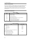
The following table lists the characteristics of AWG (American Wire Gage) copper wire.
Table 3-2. Ampacity and Resistance of Stranded Copper Conductors
AWG No. Ampacity (in free air) Resistance (at 20 deg. C)
Ω/m Ω/ft
20 8.33 0.0345 0.01054
18 15.4 0.0217 0.00663
16 19.4 0.0137 0.00417
14 31.2 0.0086 0.00262
12 40 0.0054 0.00165