


3 - Installation
28
This rear panel connector, has a fault output port and an inhibit input port. The fault (FLT) output,
also referred to as the DFI (discrete fault indicator) signal in the front panel and SCPI commands,
is an open collector circuit that pulls the positive output low with respect to the negative (chassis
referenced) common. The high impedance inhibit (INH) input, also referred to as the RI (remote
inhibit) signal in the front panel and SCPI commands, is used to shut down the power supply
output whenever the INH + is pulled low with respect to INH (chassis referenced) common.
The connector accepts wires sizes from AWG 22 to AWG 12. Disconnect the mating plug to make
your wire connections.
NOTE: It is good engineering practice to twist and shield all signal wires to and from the
digital connectors. If shielded wire is used, connect only one end of the shield to
chassis ground to prevent ground loops.
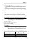
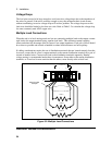
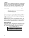
Figure 3-4 shows how you can connect the FLT/INH circuits of the dc source.
In example A, the INH input connects to a switch that shorts the Inhibit pin (+) to common
whenever it is necessary to disable output of the unit. This activates the remote inhibit (RI) circuit,
which turns off the dc output. The front panel Prot annunciator comes on and the RI bit is set in
the Questionable Status Event register. To re-enable the unit, first open the connection between
pins INH + and common and then clear the protection circuit. This can be done either from the
front panel or over the HP-IB/RS-232.
In example B, the FLT output of one unit is connected to the INH input of another unit. A fault
condition in one of the units will disable all of them without intervention either by the controller or
external circuitry. The controller can be made aware of the fault via a service request (SRQ)
generated by the Questionable Status summary bit. Note that the FLT output can also be used to
drive an external relay circuit or signal other devices whenever a user-definable fault occurs.
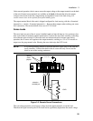
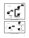
Digital I/O Connections
As shown in Table 3-3 and Figure 3-5, the FLT/INH connector can also be configured as a digital
I/O port. Information on programming the digital I/O port is found in chapter 5 and under
[SOURce:]DIGital:DATA and [SOURce:]DIGital: FUNCtion commands in the Programming
Guide. The electrical characteristics of the digital connector are described in appendix A.
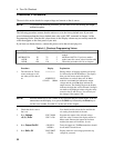
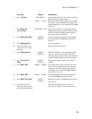
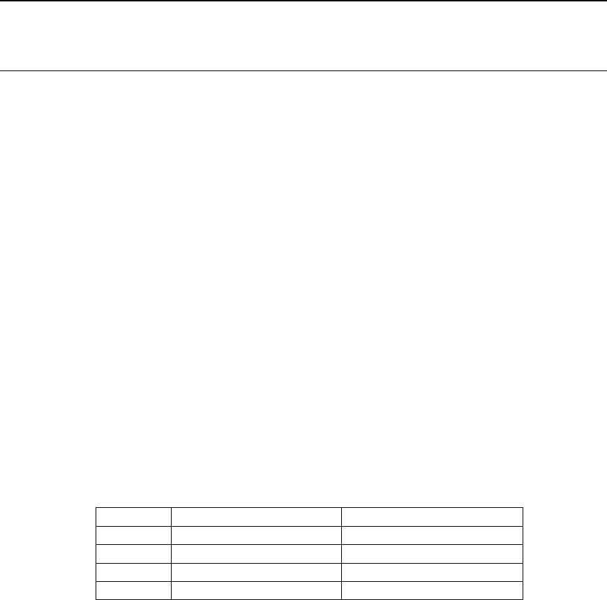
Table 3-3. FLT/INH DIGital I/O Connector
PIN FAULT/INHIBIT DIGITAL I/O
1 FLT Output Output 0
2 FLT Common Output 1
3 INH Input Input/Output 2
4 INH Common Common