


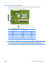
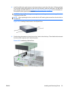
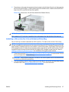
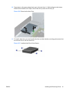

3. Press down on the green drive retainer button located on the left side of the drive to disengage the
drive from the drive cage (1). While pressing the drive retainer button, slide the drive back until it
stops, then lift it up and out of the drive cage (2).
Figure 2-31 Removing a 3.5-inch Drive (Media Card Reader Shown)
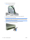
NOTE: To replace the 3.5-inch drive, reverse the removal procedure.
When replacing a 3.5-inch drive, transfer the four guide screws from the old drive to the new one.
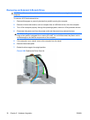
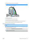
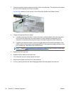
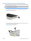
Installing a Drive into the 3.5-inch External Drive Bay
The 3.5-inch bay is located underneath the 5.25-inch drive. To install a drive into the 3.5-inch bay:
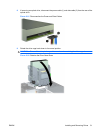
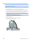
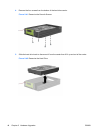
NOTE: Install guide screws to ensure the drive will line up correctly in the drive cage and lock in place.
HP has provided extra guide screws for the external drive bays (four 6-32 standard screws and four M3
metric screws), installed in the front of the chassis, under the front bezel. A secondary hard drive uses
6-32 standard screws. All other drives (except the primary hard drive) use M3 metric screws. The HP-
supplied M3 metric screws are black and the HP-supplied 6-32 standard screws are silver. Refer to
Installing and Removing Drives on page 27 for illustrations of the guide screw locations.
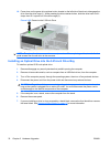
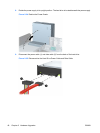
1. Follow the procedure in Removing an External 5.25-inch Drive on page 30 to remove the 5.25-inch
drive and access the 3.5-inch drive bay.
CAUTION: Ensure that the computer is turned off and that the power cord is disconnected from
the electrical outlet before proceeding.
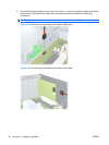
2. If you are installing a drive in a bay covered by a bezel blank, remove the front bezel then remove
the bezel blank. See
Removing Bezel Blanks on page 12 for more information.
ENWW Installing and Removing Drives 37