


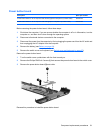
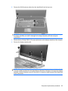

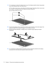
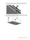
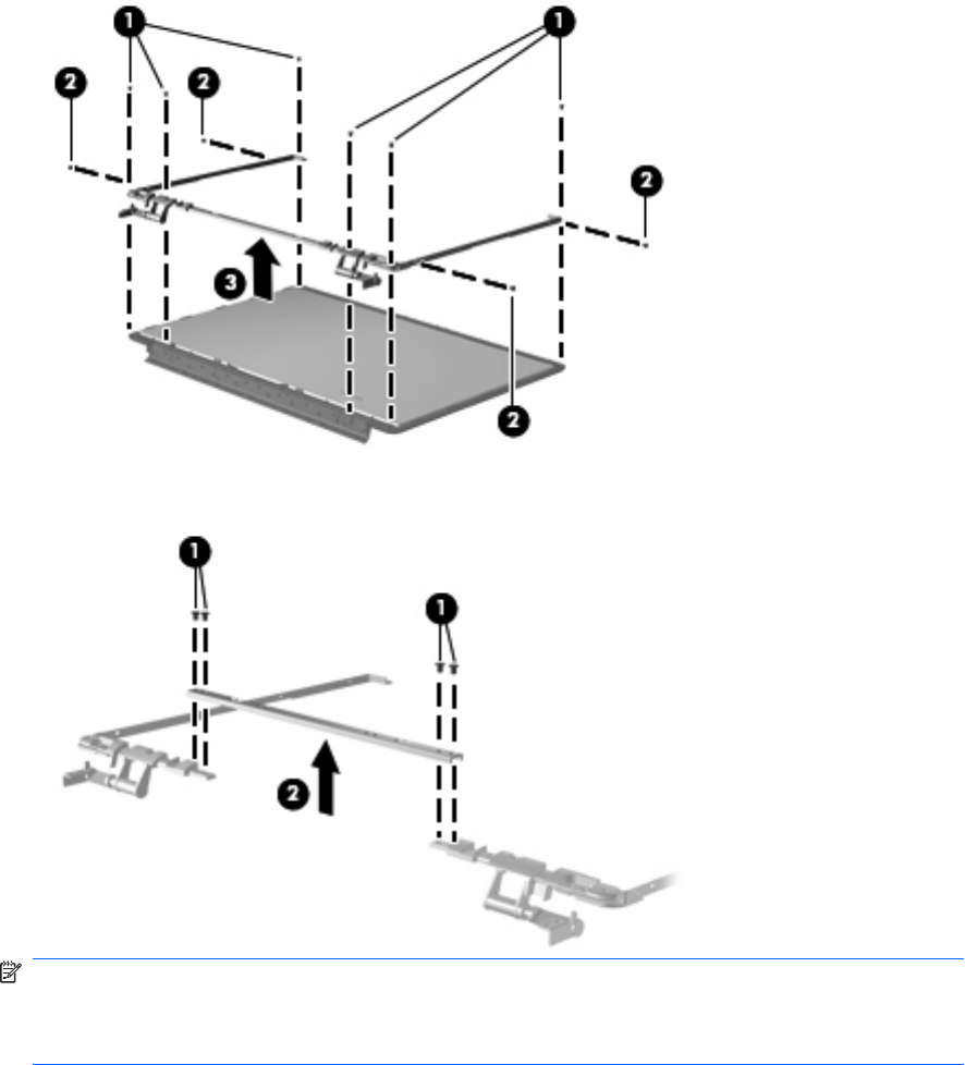
18. Remove the display hinge assembly (3) by lifting it straight up. The display hinges are available
using spare part number 516444-001. The display screw kit is available using spare part kit
531764-001.
The left and right sides of the display hinge assembly are secured using four PM 2.5×4.0
screws (1) to a bracket (2) as shown in the following image.
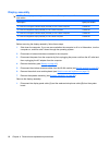
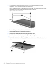
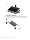
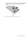
NOTE: Steps 19 through 28 provide display assembly internal component removal information
for computer models equipped with BrightView display assemblies. See steps 5 through 18 for
display assembly internal component removal information for computer models equipped with flush
glass display assemblies.
Component replacement procedures 69